VFD-C2000 PROFINET Communication Card CMC-PN01
CMC-PN01 Operation Manual
command
status
(CMDJOG=1)
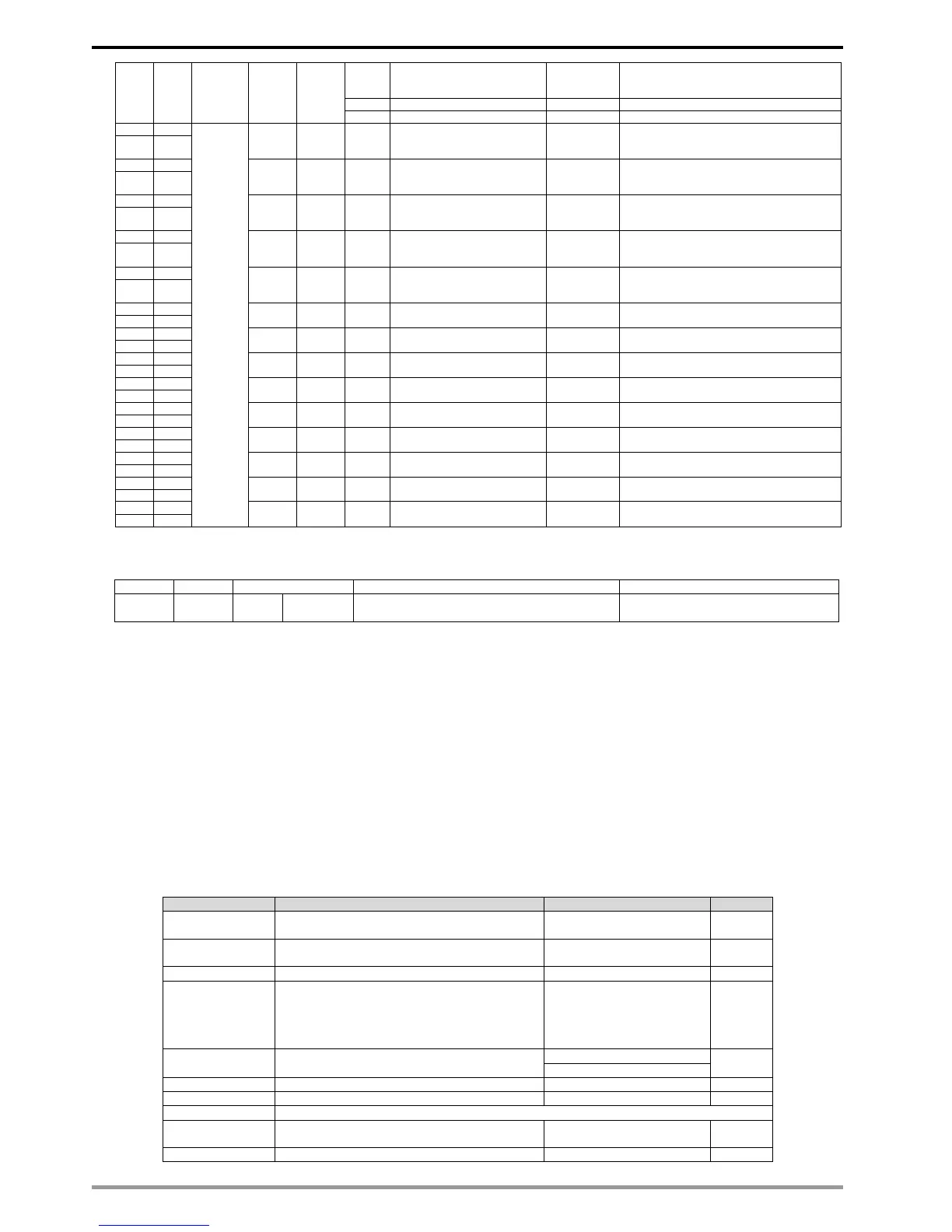
Bits in this column are used for displaying VFD’s
current running frequency command values (2dot
value) with its unit Hz.
Bits in this column are used for displaying VFD’s
current output frequency values (two-dot value) with
its unit Hz.
Bits in this column are used for displaying VFD’s
current output current values (one-dot value) with its
unit A.
Bits in this column are used for displaying VFD’s
current DC BUS voltage values (one-dot value) with
its unit V.
Bits in this column are used for displaying VFD’s
current output voltage values (one-dot value) with its
unit V.
Bits in this column are used for displaying VFD’s
current multi-step speed and frequency values.
Power factor angle (0–180.0
degree)
Table 5: Disconnection Treatment (CMC-PN01Drive)
5.2 Asynchronous Parameter Access
Host controller PROFINET sends a write request first, then CMC-PN01 determines
whether the host controller needs to read or write in accordance with the Operation field in
the packet, and read or write drive’s parameters through the contents of Data Block.
If there is no problem for the packet and CMC-PN01 is not in a busy mode, CMC-PN01
sends a write response to make the host controller be aware that CMC-PN1 has received the
packet delivered and performed corresponding actions accordingly.
If the host controller requests to read the parameters, CMC-PN01 needs to send a read
request after sending a write response. Then CMC-PN01 reads the corresponding
parameters of the drive and replies to the host controller in the packet of read response.
The table below shows the definitions of the packet:
Request or Response service.
Request (0x00)
Response (0x80)
Identifier
- time low
- time mid
- time high and version – clock – node
UI32
UI16
UI16
Qctet[2]
Qctet[6]
Application Process Identifier
Device Access Point (0x000)
Slot of the Module Access Point (MAP/PAP)
Sub-slot of the Module Access Point (MAP/PAP)
Index of the Record Data Object
This section is only allowed to be written by the
card.
This address can correspond to VFD’s
communication parameter.