EasyManuals Logo
Home>Delta>Inverter Drive>VFD-C2000

Delta VFD-C2000 User Manual

Delta VFD-C2000
51 pages
To Next Page IconTo Next Page
To Previous Page IconTo Previous Page
Page #7 background imageLoading...
Page #7 background image
VFD-C2000 PROFINET Communication Card CMC-PN01
CMC-PN01 Operation Manual
7
2.3 LED Indicators
Name
Indicator Status
Indication
Ready out indicator
Yellow LED
Always on
PN Stack normal activation
Flashing
PN Stack normal activation, waiting for
synchronizing with MCU.
Off
PN Stack abnormal activation
MT out indicator
Green LED
-
-
SD indicator
Red LED
-
-
BF out indicator
Red LED
Always on
Disconnected with PROFINET Controller
Flashing
Normal connection, but abnormal
communication with PROFINET
Controller.
Off
Normal connection with PROFINET
Controller
ACT PHY1
indicator
Orange LED
Always on
Connected and is exchanging data with
Master regularly
Flashing
Not connected but is handshaking data
with Master
Off
Initial status
LINK PHY1
indicator
Green LED
Always on
Normal network connection
Off
Not connected to network
ACT PHY2
indicator
Orange LED
Always on
Connected and is exchanging data with
Master regularly
Flashing
Not connected but is handshaking data
with Master
Off
Initial status
LINK PHY2
indicator
Green LED
Always on
Normal network connection
Off
Not connected to network
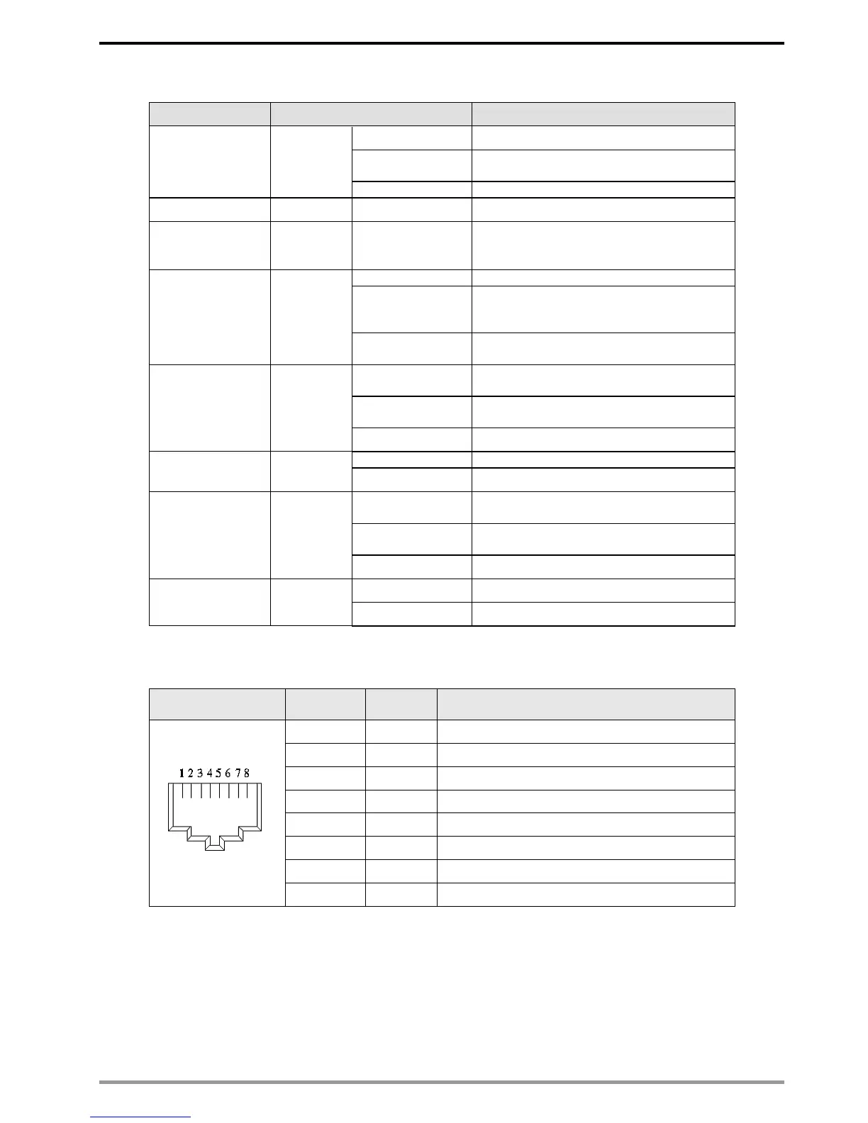
2.4 Definition of RJ45 Pin
RJ45 Pinout
Diagram
PIN
Definition
Description
1
Tx+
Positive pole for data transmission
2
Tx-
Negative pole for data transmission
3
Rx+
Positive pole for receiving data
4
--
N/C
5
--
N/C
6
Rx-
Negative pole for receiving data
7
--
N/C
8
--
N/C

Questions and Answers:

Question and Answer IconNeed help?

Do you have a question about the Delta VFD-C2000 and is the answer not in the manual?

Delta VFD-C2000 Specifications

General IconGeneral
BrandDelta
ModelVFD-C2000
CategoryInverter Drive
LanguageEnglish