EasyManua.ls Logo

Delta VFD-C2000 User Manual

Delta VFD-C2000
51 pages
To Next Page IconTo Next Page
To Previous Page IconTo Previous Page
Page #32 background imageLoading...
Page #32 background image
VFD-C2000 PROFINET Communication Card CMC-PN01
CMC-PN01 Operation Manual
32
Below is the STEP 7 program-editing screen and an example of writing a program by using 20xx
message format.
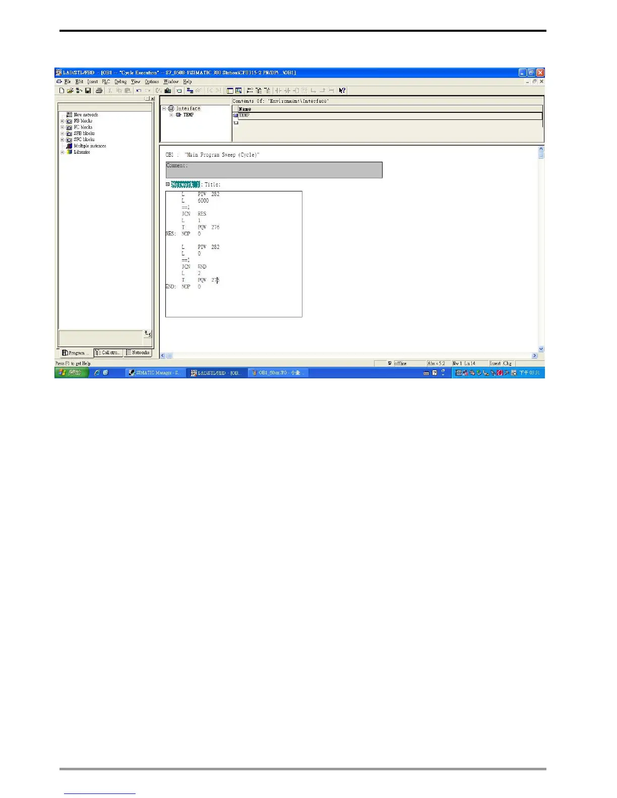
1. PIW282 means 2103H (output frequency).
2. PQW276 means 2000H (control word).
3. The writing of the program explains as follows.
OB1 Program (Main Loop) is explained as follows:
a. Judging if PIW282 (2103H) equals to 6000. If YES, PQW276 (2000H) equals to 1, which
means the drive stops running; if NO, go to RES label;
b. Judging if PIW282 (2103H) equals to 0. If YES, PQW276 (2000H) equals to 2, which
means the drive starts running; if NO, go to END label;
Therefore, the drive performs continuous actions of running until stop, and then starts
running again.
Question and Answer IconNeed help?

Do you have a question about the Delta VFD-C2000 and is the answer not in the manual?

Delta VFD-C2000 Specifications

General IconGeneral
BrandDelta
ModelVFD-C2000
CategoryInverter Drive
LanguageEnglish

Summary

Caution

1 Introduction

1.1 Introduction to PROFINET IO Communication

Overview of PROFINET IO communication protocol and its channels.

1.2 Features

Key features and benefits of the CMC-PN01 communication card.

1.3 Network Functions and Specifications

Technical specifications for Ethernet and environmental conditions.

2 Product Appearance and Components

2.1 Exterior Dimensions

Physical dimensions of the communication card.

2.2 Introduction to Each Component

Identification of physical components on the communication card.

2.3 LED Indicators

Meaning of different LED status indicators on the card.

2.4 Definition of RJ45 Pin

Pinout definition for the RJ45 connector.

2.5 MAC Address Label

Location and format of the MAC address label.

3 Installation and Wiring

3.1 Installation

Step-by-step guide for installing the CMC-PN01 card into the drive.

3.2 Unloading

Procedure for detaching the CMC-PN01 card from the drive.

3.3 Connecting to the Network

Wiring diagram and steps for connecting the card to a PROFINET network.

4 VFD-C2000 Drive Settings

5 PROFINET Communication Profile

5.1 Synchronous Parameter Access in Delta-specific Mode (Tables for Control Word and Status Word)

Detailed tables for synchronous parameter exchange between controller and drive.

5.2 Asynchronous Parameter Access

How the host controller reads/writes parameters asynchronously.

5.3 Identification and Maintenance Functions (I&M)

Support for adjustment, test, and repair using I&M functions.

5.4 Disconnection Treatment

Actions taken by the card upon PROFINET disconnection.

6 Connection Configuration to Host Controller

6.1 Basic Configuration

Initial PC and IP address setup for communication.

6.2 Speed Mode DEMO (S7-300 + STEP 7)

Demonstration of speed mode configuration using S7-300 and STEP 7.

6.3 Speed Mode DEMO (S7-1500 + TIA PORTAL)

Demonstration of speed mode configuration using S7-1500 and TIA PORTAL.

6.4 Demonstration of Reading/Writing Synchronous and Asynchronous Parameters (S7-300 + TIA PORTAL)

Steps for reading/writing drive parameters using S7-300 and TIA Portal.