Chapter 7 Option Cards | VFD-ED
7-2-5 Frequency Division Signal Setting
1. After the encoder inputs a PULSE signal, there is an output signal by the division factor “n” Set
the value in Pr.10-29 (PG card’s frequency division output).
2. Set Pr.10-29 (PG card’s frequency division output): The decimal frequency division output
setting; range of the division factor “n”: 1–31.
3. Pr.10-30 (PG card’s frequency division output mode)
Bit3 Bit2 Bit1 Bit0
X X OUT/M
IN/M
OUT/M: Pulse output mode for frequency division;
IN/M: Pulse input mode for frequency division;
“X” is for backup while “0” is a value to write.
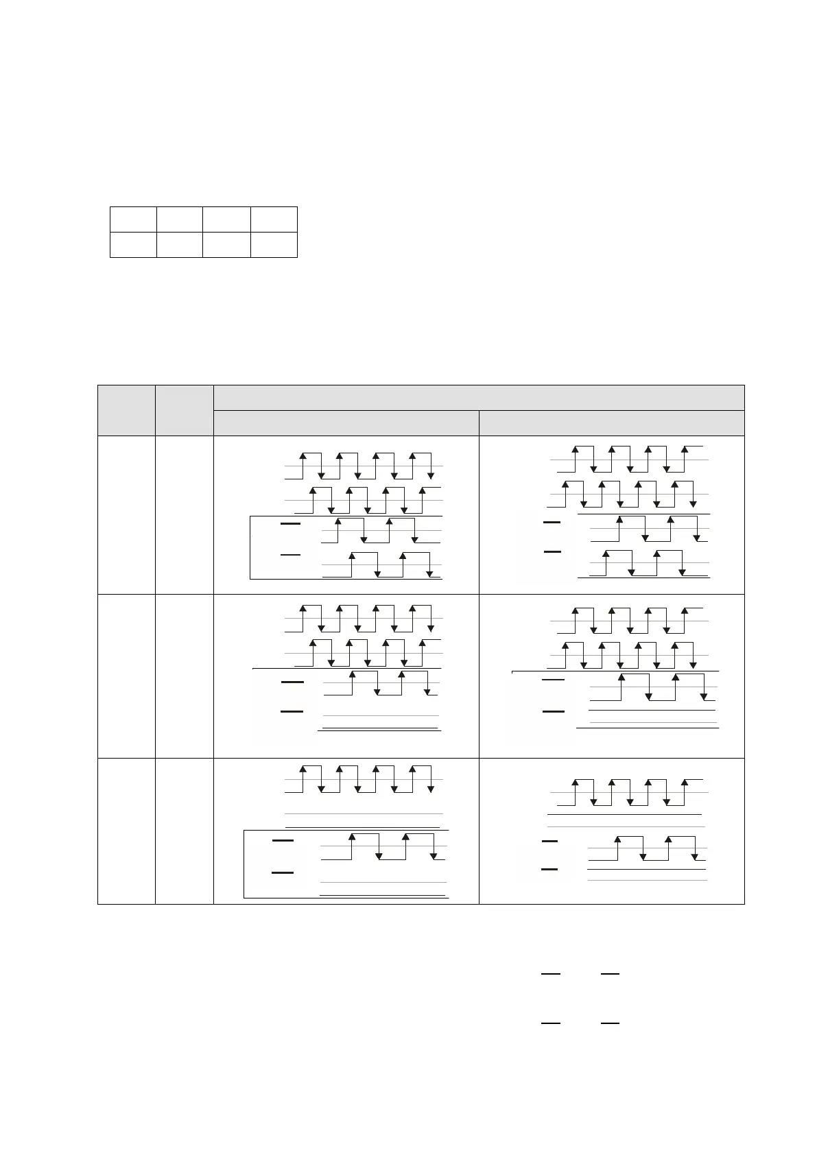
The following table lists the Input Mode (IN/M) & Output Mode (OUT/M) setting and description:
OUT/M IN/M
Division Factor
A is ahead of B B is ahead of A
0 0
A/ O-/A/O
B/O-/B/O
A/ O-/A/O
B/O-/B/O
1 0
A/O-/A/O
B/O-/B/O
A/O-/A/O
B/O-/B/O
A/O-/A/O
B/O-/B/O
A/O-/A/O
B/O-/B/O
X 1
A/O-/A/O
B/O-/B/O
A/O-/A/O
B/O-/B/O
A/O-/A/O
B/O-/B/O
A/O-/A/O
B/O-/B/O
Table 7-1
NOTE:
In the waveform, A-/A, B-/B are the PG card input signals; AO-
, BO-
are the differential
output frequency division signals. Use a differential probe to measure.
In the
waveform
, A-/A, B-/B are the PG card input signals; AO-
, BO-
are the differential
output frequency division signals. Use a differential probe to measure.
Division factor “n”: Set 15 to divide the input signal by 15.

 Loading...


