Chapter 7 Option Cards | VFD-ED
Terminal Function
Terminals Descriptions Specifications
TB2
Up (VP)
The output voltage for
the encoder. Use the
SW2 DIP switch to
change the output
voltage to +5 V or +8 V.
Voltage: +5.1 V
DC
± 0.3 V; +8.4 V
DC
± 1.5 V
Current: 200 mA max.
0 V
Encoder common
power terminal
Reference level for the encoder’s power.
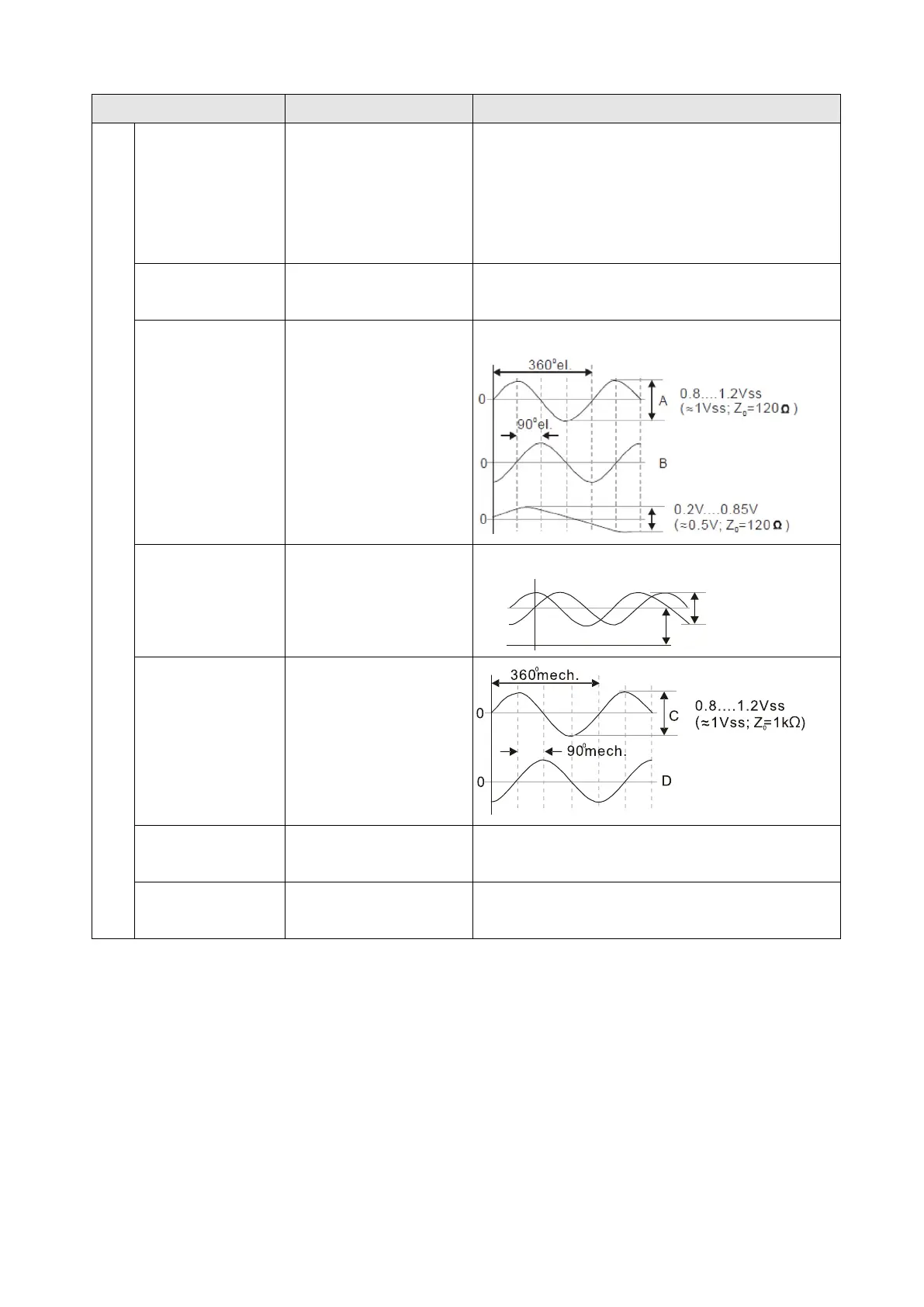
A+, A-, B+, B-,
R+, R-
Encoder sine wave
differential signal input
(incremental signal)
Input frequency: 40 kHz max.
+SIN, +COS,
REFSIN, REFCOS
Encoder sine wave
differential signal input
(incremental signal)
Input frequency: 20 kHz max.
SIN
COS
0.9...1.1V
REFSIN/REFCOS
C+, C-, D+, D-
Encoder sine wave
differential signal input
(absolute signal)
DATA+(DATA),
DATA-(/DATA)
RS-485
interface
Terminal resistance is about 130 Ω.
CLOCK+, CLOCK-
CLOCK differential
output for ENDAT
Line driver RS422 level output
NOTE:
Verify that the SW2 switch is set to the correct output voltage before powering on.
Keep the motor drive wiring away from any high voltage lines to avoid interference.

 Loading...


