Chapter 9 Digital KeypadVFD-ED
2. Edit the Main Page and Download to the Keypad
(1)
In the Editor, add a page to edit. On the Edit menu, click Add a New Page. You can also right-click on the
TP page in the upper right corner of the Design window and click Add to add one more page to edit. This
keypad currently supports up to 256 pages.
(2) In the bottom right-hand corner of the Editor, click the page number to edit, or on the View menu, click HMI
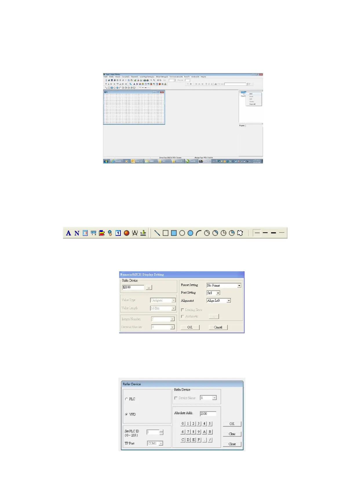
Page to start editing the main page. As shown in the picture above, the following objects are available.
From left to right they are: Static Text, ASCII Display, Static Bitmap, Scale, Bar Graph, Button, Clock Display,
Multi-state bit map, Units, Numeric Input, the 11 geometric bitmaps, and lines of different widths. Use the
same steps to add Static Text, Static Bitmap, and geometric bitmaps as for the start-up page.
(3) Add a numeric/ASCII display. On the toolbar, click the Numeric/ASCII button. In the page, double-click
the object to specify the Refer Device, Frame Setting, Font Setting and Alignment.
Click […]. In the Refer Device dialog box, choose the VFD communication port that you need. If you want
to read the output frequency (H), set the Absolute Addr. to 2202. For other values, refer to Appendix B-4
ACMD Modbus Comm Address List in this user manual.

 Loading...


