12 Descriptions of Parameter Settings | VFD-ED
Settings
Functions Descriptions
0 No function MO has no function
1
Indication during operation
Active when there is an output from the drive or RUN command is
ON.
2
Operation speed reached Active when the AC motor drive reaches the output frequency setting.
3
Desired frequency 1 reached
(Pr.02-25, 02-26)
Active when the desired frequency (Pr.02-25, 02-26) reached.
4
Desired frequency 2 reached
(Pr.02-27, 02-28)
Active when the desired frequency (Pr.02-27, 02-28) reached.
5
Zero Speed
(Frequency command)
Active when the Frequency command = 0. (the drive should be at
RUN mode)
6
Zero Speed with stop
(Frequency command)
Active when Frequency command = 0 or Stop.
7
Over-torque (OT1)
(Pr.06-05–06-07)
Active when detecting over-torque. Refer to Pr.06-05 (over-torque
detection-OT1), Pr.06-06 (over-torque detection level-OT1) and Pr.06-
07 (over-torque detection time-OT1).
8
Over-torque (OT2)
(Pr.06-08–06-10)
Active when detecting over-torque. Refer to Pr.06-08 (over-torque
detection-OT2), Pr.06-09 (over-torque detection level-OT2) and Pr.06-
10 (over-torque detection time-OT2).
9
Drive is ready Active when the drive is ON and no error detected.
10
User-defined low-voltage
detection
Active when the DC bus voltage is too low (see Pr.06-00 Low voltage
level).
11
Malfunction indication Active when a fault occurs (except Lv stop).
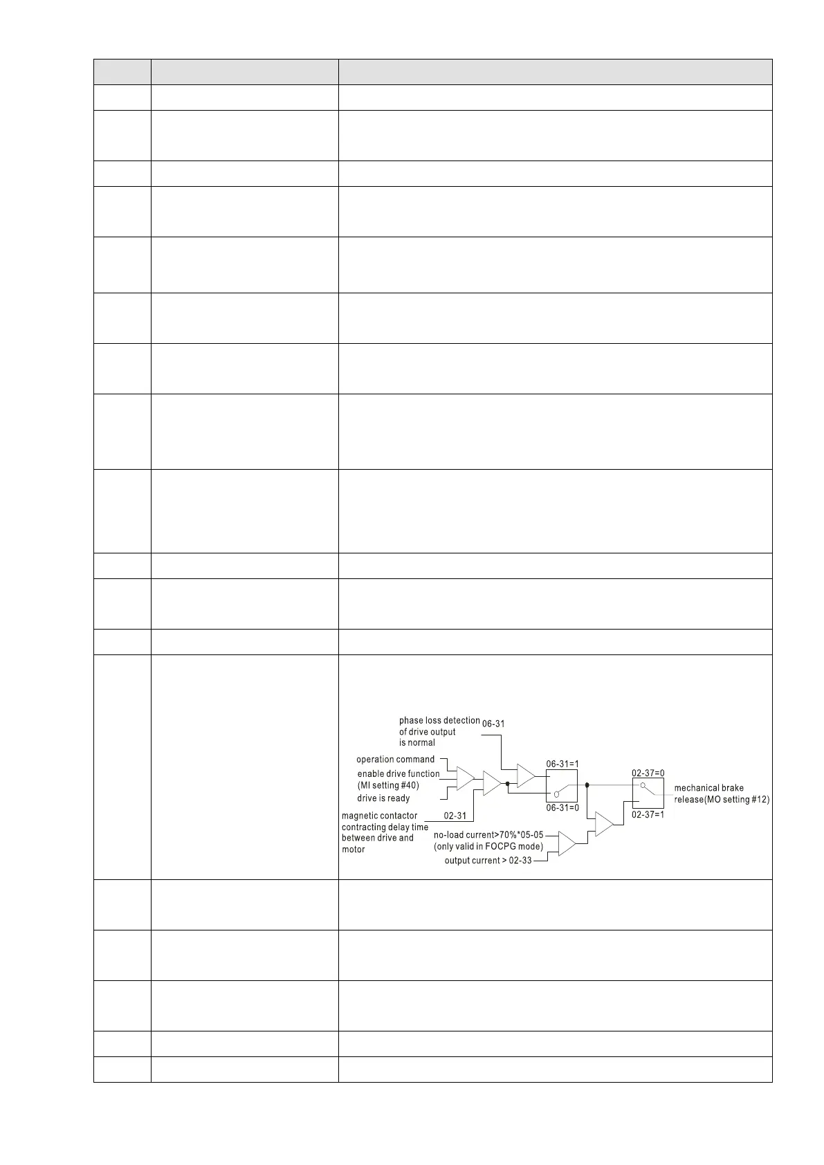
12
Mechanical brake release
(Pr.02-29, Pr.02-30, Pr.02-37)
When the drive runs according to Pr.02-29, it is ON. Use this function
with the DC brake. It is recommended to use contact “b” (N.C).
13
Overheat (Pr.06-14)
Active when IGBT or heat sink overheats. To prevent OH, turn off the
drive (refer to Pr.06-14).
14
Brake transistor signal
Activated when the drive needs help braking the load. This function
helps achieve a smooth deceleration (refer to Pr.07-00).
15
Motor-controlled magnetic
contactor output
Active when you set MI function to #40 (Enable drive function).
16
Slip error (oSL) Active when the slip error is detected (according to Pr.05-14).
17 Malfunction indication 1 Activate after 10 ms when a fault occurs (except Lv stop).

 Loading...


