12 Descriptions of Parameter Settings | VFD-ED
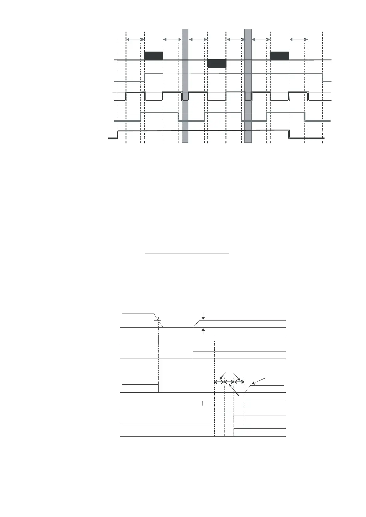
Output Frequency
Mot o r's E lec tro -
DC B rak ing
Mec ha ni cal B rake
Up/Down Command
A
B
C
E
F
G
D
C
F
C
F
B
ED
B
E
magnetic Valve
-31: Magnetic Contactor Contracting Delay
Time between Drive and Motor
-29: Brake Release Delay Time when Elevator
Starts
Pr.07-03: DC Brake Activation Time
-47: Power Generation Direction Search Time
-30: Brake Engage Delay Time when
Elevator Stops
-04: DC Brake Stopping Time
Pr.02-32: Magnetic Contactor Release
Delay Time between Drive and
Motor
Auto-detection Timing Diagram
FOCPG/PM Control Mode: In the time setting in Pr.06-47, the drive remains at zero-speed and it is able
to determine the elevator loading without performing forward/reverse run. Then the elevator operates in
the power regeneration direction (the motor is in power generating status). Refer to the diagram below
for the Auto-Detection Timing Graph.
ON
ON
Power Generatio n Dire ction
Searching Time
06-44
ON
ON
ON
07-03
06-47
Drive's DC vo lt age
Output Frequ ency
Operation comma nd
F WD /RE V
Emergency pow er
det ect ion
MI= 43
DC br ake t ime
Operation spe ed
of enege ncy power
Drive is ready
MO=9
Low voltage level
Emergency DC voltage
MO=31
Power generation
direction searching
MO=32
Power generation
direction

 Loading...


