Chapter 12 Descriptions of Parameter Settings | VFD-ED
2: 7, E, 1 for ASCII
3: 7, O, 1 for ASCII
4: 7, E, 2 for ASCII
5: 7, O, 2 for ASCII
6: 8, N, 1 for ASCII
7: 8, N, 2 for ASCII
8: 8, E, 1 for ASCII
9: 8, O, 1 for ASCII
10: 8, E, 2 for ASCII
11: 8, O, 2 for ASCII
12: 8, N, 1 for RTU
13: 8, N, 2 for RTU
14: 8, E, 1 for RTU
15: 8, O, 1 for RTU
16: 8, E, 2 for RTU
17: 8, O, 2 for RTU
Control by PC (Computer Link)
When using the RS-485 serial communication interface, you must specify each drives
communication address in Pr.09-00. The computer then implements control using the drive’s
individual addresses.
Modbus ASCII (American Standard Code for Information Interchange): Each byte of data is the
combination of two ASCII characters. For example, one byte of data: 64 Hex, shown as ‘64’ in
ASCII, consists of 6 (36Hex) and 4 (34Hex).
Control Mode
VF VFPG SVC FOCPG FOCPM Default: 2.0
Settings 0.0–200.0 ms
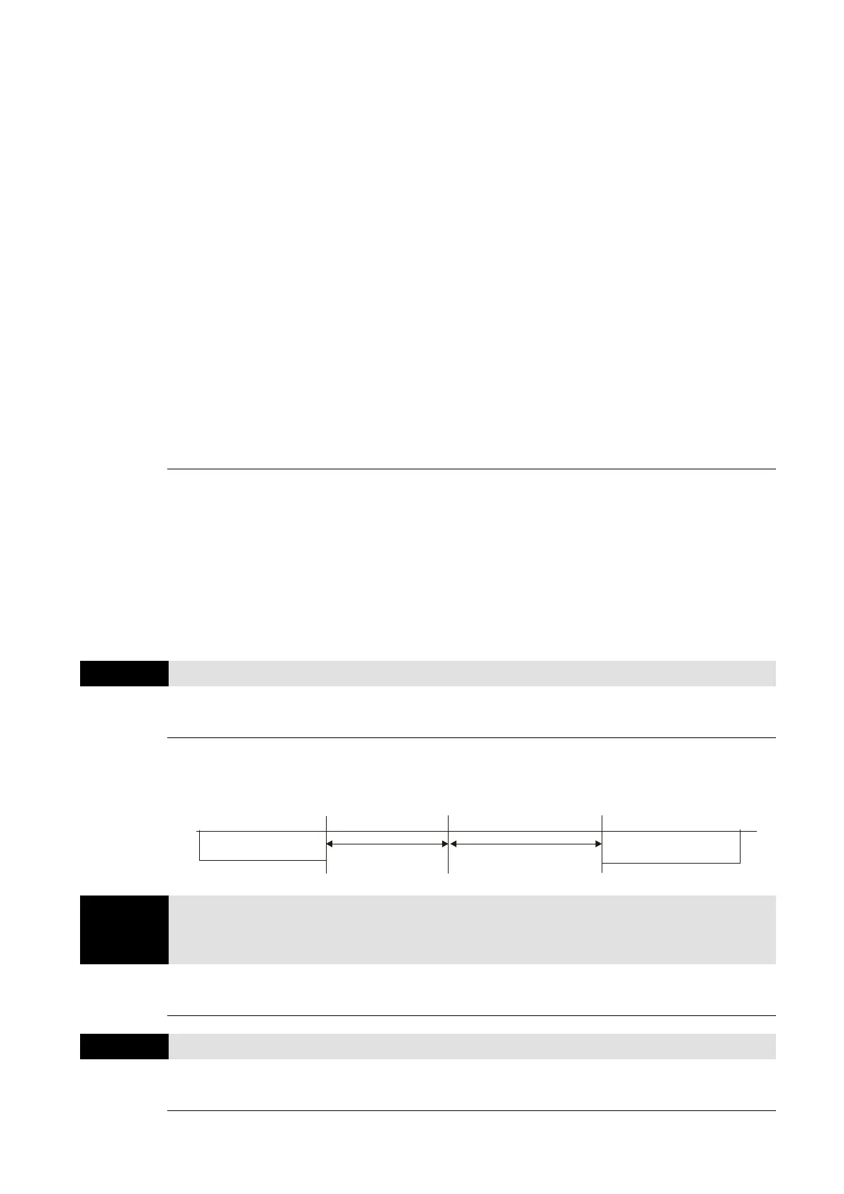
If the host computer does not finish the transmitting/receiving process, you can use this parameter
to set the response delay time after the AC motor drive receives communication command as
shown in the following picture.
PC or PLC command
Handling time
of the AC drive
Response Delay Time
Response Message
of the AC Drive
RS-485 BUS
–
Direct Docking Mode Only
Control Mode
Default: -
Settings Contact Delta for more information
PDO Transmission Interval
Control Mode
VF VFPG SVC FOCPG FOCPM Default: 0
Settings 0–65535 ms

 Loading...


