12 Descriptions of Parameter Settings | VFD-ED
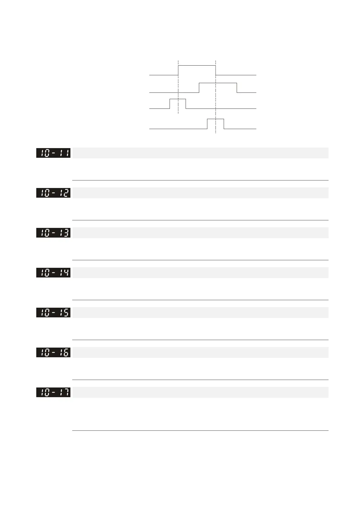
0: The operation is U->V->W, Z signal is at the falling edge of U-phase.
1: The operation is U->V->W, Z signal is at the rising edge of U-phase.
U
V
Pr.10-10=1
Pr.10-10=0
Z Signal
Z Signal
ASR (Auto Speed Regulation) Control (P) of Zero Speed
Control Mode
VF VFPG SVC FOCPG FOCPM Default: 100.0
Settings 0.0–1000.0%
ASR (Auto Speed Regulation) Control (I) of Zero Speed
Control Mode
VF VFPG SVC FOCPG FOCPM Default: 0.100
Settings 0.000–10.000 sec.
ASR (Auto Speed Regulation) Control (P) 1
Control Mode
VF VFPG SVC FOCPG FOCPM Default: 100.0
Settings 0.0–1000.0%
ASR (Auto Speed Regulation) Control (I) 1
Control Mode
VF VFPG SVC FOCPG FOCPM Default: 0.100
Settings 0.000–10.000 sec.
ASR (Auto Speed Regulation) Control (P) 2
Control Mode
VF VFPG SVC FOCPG FOCPM Default: 100.0
Settings 0.0–1000.0%
ASR (Auto Speed Regulation) Control (I) 2
Control Mode
VF VFPG SVC FOCPG FOCPM Default: 0.100
Settings 0.000–10.000 sec.
ASR 1/ASR2 Switch Frequency
Control Mode
VF VFPG SVC FOCPG FOCPM Default: 7.00
Settings 0.00–299.00 Hz
0: Disable
ASR P determines the proportional control and associated gain (P). ASR I determines the integral control
and associated gain (I).
When you set the integral time to 0, it is disabled. Pr.10-17 defines the switch frequency for the ASR1
(Pr.10-13, Pr.10-14) and ASR2 (Pr.10-15, Pr.10-16).

 Loading...


