Chapter 4 Main Circuit Terminals | VFD-ED
Tighten the screws in the main circuit terminal to prevent sparks caused by screws
loosened due to vibration.
Ensure proper insulation of the main circuit wiring in accordance with the relevant
safety regulations.
Main input power terminals
Do not connect a three-phase model to single-phase power. R/L1, S/L2 and T/L3 have
no phase-sequence requirement and can be connected in any sequence.
You must install a NFB between the three-phase power input terminals and the main
circuit terminals (R/L1, S/L2, T/L3). Add a magnetic contactor (MC) to the power input
wiring to cut off powe
r quickly and reduce malfunctions when the AC motor drive
protection function activates. Both ends of the MC should have an R-C surge absorber.
Use voltage and current within the specifications in Chapter 8.
When using a general ELB (Earth Leakage Breaker), select a current sensor with
sensitivity of 200 mA or above and not less than 0.1 second operation time to avoid
nuisance tripping. When choosing an ELB designed for the AC motor drive, choose a
current sensor with sensitivity of 30 mA or above.
Use shielded wire or conduit for the power wiring and ground the two ends of the
shielding or conduit.
Do NOT run and stop the AC motor drives by turning the power ON and OFF. Run
and stop the AC motor drives by sending the RUN and STOP commands through the
control terminals or the keypad. If you still need to run and stop the AC motor drives
by turning the power ON and OFF, do so no more often than ONCE per hour.
Output terminals of the main circuit
When it is necessary to install a filter at the output side of the AC motor drive terminals
U/T1, V/T2, W/T3, use an inductance filter. Do not use phase-compensation capacitors
or L-C (Inductance-Capacitance) or R-C (Resistance-Capacitance) capacitors.
DO NOT connect phase-compensation capacitors or surge absorbers at the output
terminals of AC motor drives.
Use well-insulated motors to prevent any electric leakage from the motors.
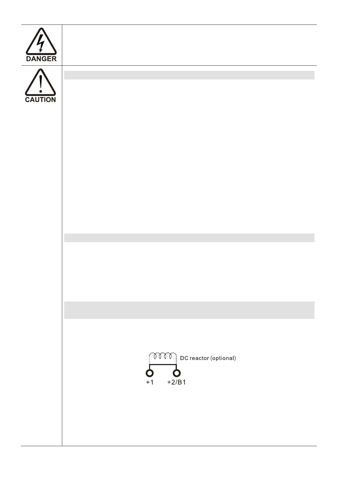
Use terminals [+1, +2] for connecting a DC reactor.
Use terminals [+1, +2/B1] for connecting a DC bus.
Use these terminals to connect a DC reactor to improve the power factor and reduce
harmonics. A jumper is connected to these terminals at the factory. Remove that
jumper before connecting to a DC reactor.
Figure 4-1
Models above 22 kW do not have a built-in brake resistor. To improve resistance
braking, connect an optional external brake resistor.
When not in use, leave terminals +2/B1, [-] open.
Short-circuiting [B2] or [-] to [+2/B1] damages the motor drive. Do NOT short-circuit
those terminals.

 Loading...


