Chapter 16 Safe Torque Off Function | VFD-ED
16-3-3 Drive’s Control Circuit Wiring Diagram
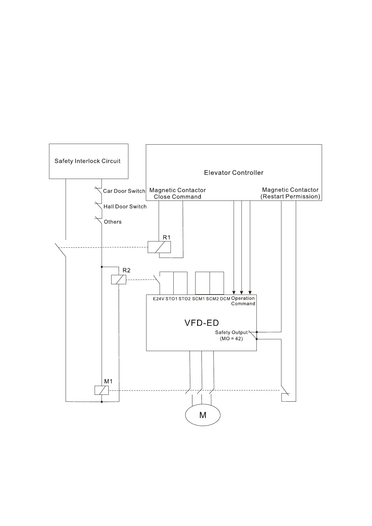
1. Remove the E24V-STO1-STO2 short circuit.
2. Figure 16-4 below shows the wiring. The contract for safety interlock circuit must be closed
during the normal situation so that the motor drive can run.
3. In STO mode, if you switch on the safety interlock circuit, the motor drive stops outputting and
the keypad displays STO.
4. If the restart permission signal is OFF before the elevator controller issues the command to
start the elevator, it means that the STO function is currently malfunctioned or M1 magnetic
contactor error has occurred, and then the elevator is unable to start (R1 cannot be ON).
Figure 16-4
NOTE: R” in R1/R2 stands for Relay; “M” in M1 stands for MC (Magnetic Contactor)
 Loading...


