Appendix B. Modbus ProtocolVFD-ED
This appendix helps users to control by computers and monitor drive parameters and status
through Modbus by using RS-485 serial communication interface
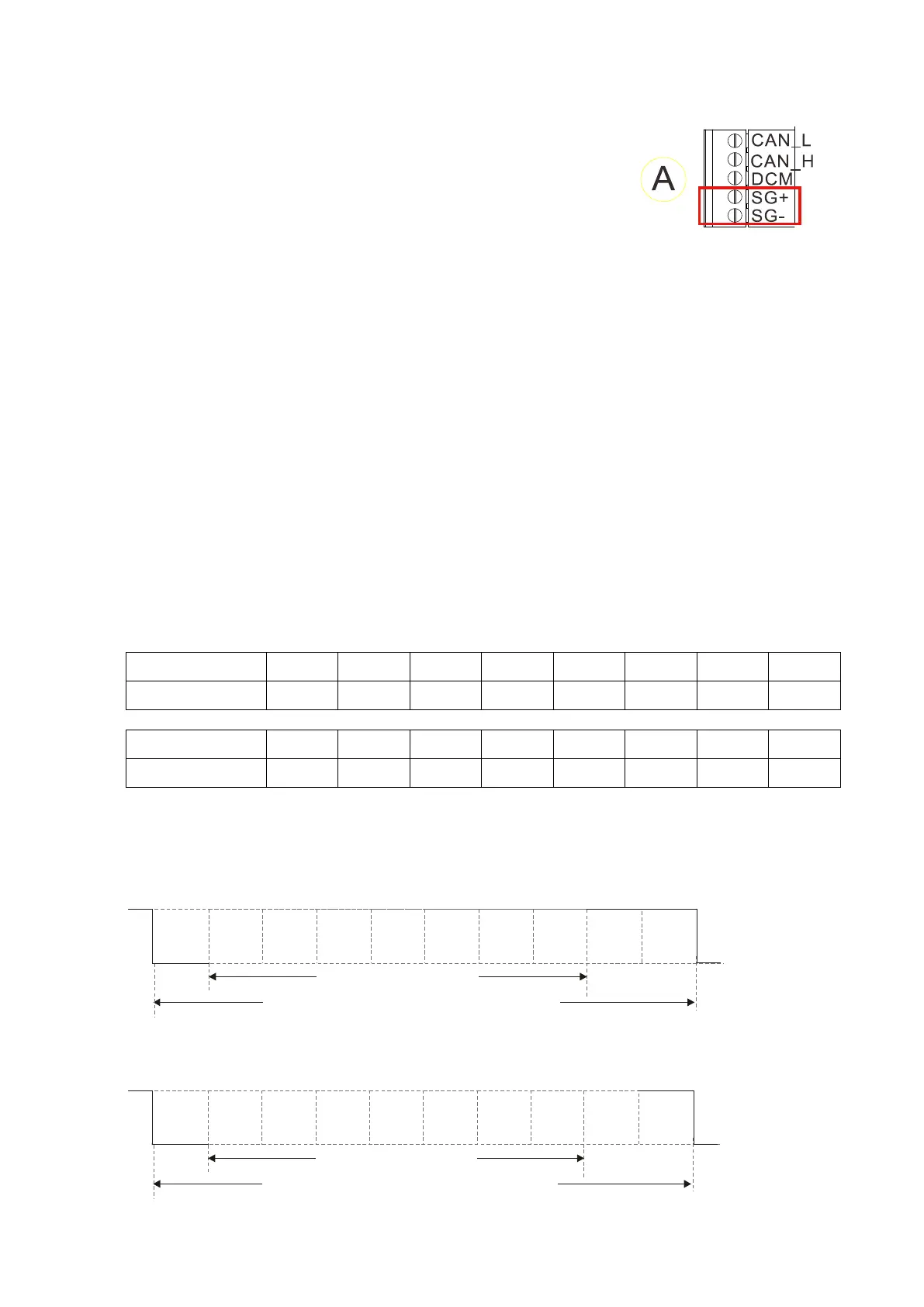
When using the communication interface, the diagram on the
right shows the communication port pin definitions. It is
recommended that you connect the AC motor drive to your
using Delta IFD6530 or IFD6500 as a communication converter.
For details on communication port as the right diagram shows,
see the lower right corner in Figure 3-5 in Chapter 3 Wiring.
The default communication formats for communication port:
1. Modbus ASCII mode
2. 9600 bps serial communication baud rates
3. 7-bit data character
4. No parity bit
5. 2 stop bit
Modbus ASCII (American Standard Code for Information Interchange): Each byte of data is the
combination of two ASCII characters. For example, one byte of data: 64 Hex, shown as ‘64’ in
ASCII, consists of ‘6’ (36Hex) and ‘4’ (34Hex)
B-1 Code Description
The communication protocol is in hexadecimal, ASCII: “0”…“9”, “A”…“F”, every hexadecimal value
represents an ASCII code. The following table shows some examples.
Character ‘0’ ‘1’ ‘2’ ‘3’ ‘4’ ‘5’ ‘6’ ‘7’
ASCII code 30H 31H 32H 33H 34H 35H 36H 37H
Character ‘8’ ‘9’ ‘A’ ‘B’ ‘C’ ‘D’ ‘E’ ‘F’
ASCII code 38H 39H 41H 42H 43H 44H 45H 46H
B-2 Data Format
1. 10-bit character frame (For ASCII)
(7, N, 2)
Start
bit
0 1
2
3 4 5 6
Stop
bit
7-data bits
10-bits character frame
Stop
bit
(7, E, 1)
Even
parity
Start
bit
0 1
2
3 4 5 6
Stop
bit
7-data bits
10-bits character frame
(7, O, 1)

 Loading...


