Chapter 12 Description of Parameter SettingsMS300 (High Speed Model)
12-00-6
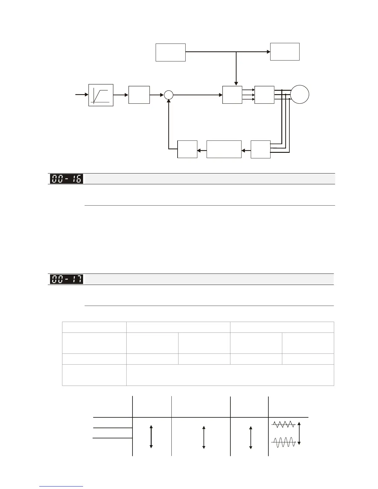
When Pr. 00-10 = 0 and set Pr. 00-11 to 0, the V/F control diagram is shown as follows:
Fcmd
Pr. 00-20
AVR
07-23
Irms
M
IGBT
PWM
01-00
01-01
01-02
05-01
05-02
05-03
05-04
DC BUS
V/F
table
Voltage
Detection
Protection
Accel. / Decel. time
DC BUS Voltage
Current Detection
01-00,01-01
01-02,01-03
01-04,01-05
01-06,01-07
01-08
Torque
Compensation
LPF
07-24
07-26
Compensation
voltage
X
+
+
Load Selection
Factory Setting: Ready only
Settings 1: Heavy load
Heavy duty: over load rated output current 200 % in 3 seconds. (150 %,1 minutes) Please refer to
Pr. 00-17 for the setting of carrier wave. Refer to Pr. 00-01 or specification table for the rated
current.
In Heavy Duty, the default setting of Pr. 06-03 and Pr. 06-04 is 180 %, maximum is 200 %.
However, if DC voltage is higher than 700 VDC (460V series) or 350V (230V series), then the
maximum will be 165 %
Carrier Frequency
Factory Setting: 6
Settings Heavy load: 2~15 KHz
This parameter determinates the PWM carrier frequency of the AC motor drive.
Series 230V 460V
Models
1~15HP
[0.75~11kW]
20~30HP
[15~37kW]
1~20HP
[0.75~15kW]
25~40HP
[18.5~55kW]
Settings Range
02~15kHz 02~10kHz 02~15kHz 02~10kHz
Heavy Duty
Factory Setting
6 kHz
2 kHz
8 kHz
15 kHz
Carrier
Frequency
Acoustic
Noise
Electromagnetic
Noise or Leakage
Current
Heat
Dissipation
Current
Wave
Significant
Minimal
Minimal
Minimal
Significant
Significant
 Loading...


