Chapter 12 Description of Parameter SettingsMS300 (High Speed Model)
12-01-4
V/F curve setting is usually set by the motor’s allowable loading characteristics. If the loading
characteristics exceed the loading limit of the motor, must pay more attention to the heat
dissipation, dynamic balance, and bearing lubricity of the motor.
If the voltage is too high at low frequency, it may cause motor damage, overheat, and stall
prevention or over-current protection. To prevent motor damage or motor fault, please be careful
when setting the voltage.
Pr. 01-35 ~ Pr. 01-42 is the V/F curve for motor 2. When multi-function input terminals Pr. 02-01 ~
02-08 and Pr. 02-26 ~ Pr. 02-31 (extension card) are set to 14 and enabled, the AC motor drive
will act as the 2
nd
V/F curve.
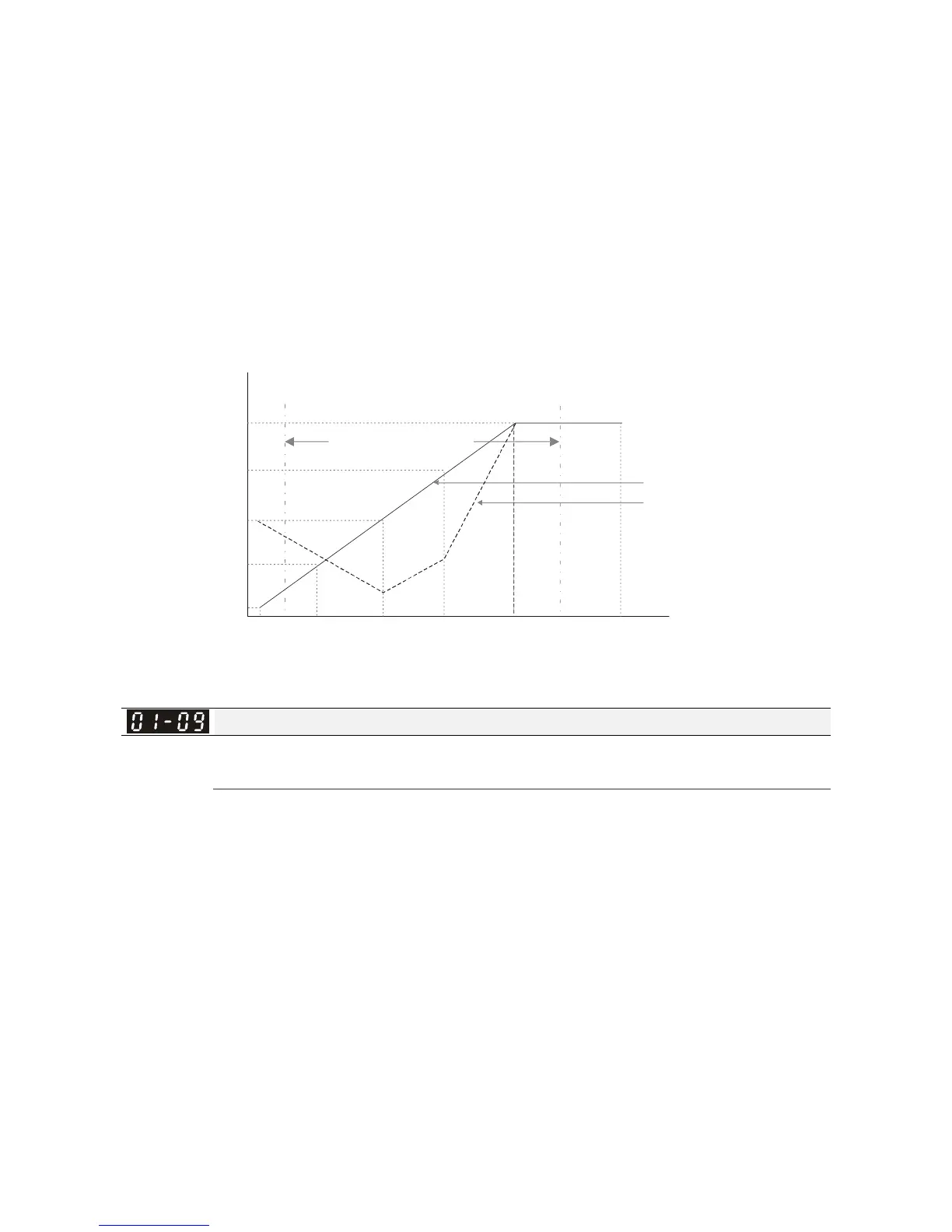
The V/F curve for motor 1 is shown as follows. The V/F curve for motor 2 can be deduced from it.
1st Voltage
Frequency lower limit
Frequency output
limit range
Regular V/F Curve
Special V/F Curve
Voltage
4th Freq.
Start Freq. 3rd Freq.
2nd Freq.
1st Freq.
Maximum output
frequency
2nd Voltage
3rd Voltage
4th Voltage
Frequency upper limit
Frequency
01-05 01-03 01-01
01-06
01-04
01-02
01-00
V/F Curve
01-07
01-08
01-09
01-11 01-10
Start-up Frequency
Factory Setting: 0.5
Settings 0.0~1500.0 Hz
When start frequency is higher than the min. output frequency, drive’s output will be from start
frequency to the setting frequency. Please refer to the following diagram for details.
Fcmd = frequency command;
Fstart = start frequency (Pr. 01-09);
fstart = actual start frequency of drive;
Fmin = 4th output frequency setting (Pr. 01-07 / Pr. 01-41);
Flow = output frequency lower limit (Pr. 01-11)
When Fcmd > Fmin and Fcmd < Fstart:
If Flow < Fcmd, drive will run directly by Fcmd.
If Flow ≥ Fcmd, drive will run by Fcmd, then rise to Flow according to acceleration time.
The output frequency will attain directly to 0 when decelerating to Fmin.
 Loading...


