Chapter 16 PLC Function ApplicationsMS300 (High Speed Model)
16-19
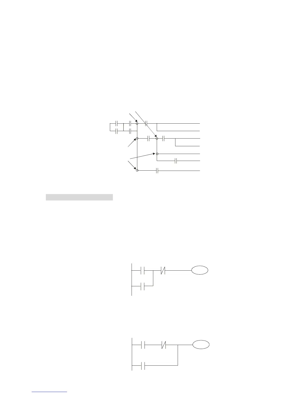
MPS can be distinguished by use of the "┬" symbol; this command can be used consecutively for up
to 8 times. The MRD command is read from branching point memory; because logic states along any
one vertical line must be the same, in order to continue analysis of other ladder diagrams, the original
contact status must be read.
MRD can be distinguished by use of the "├" symbol. The MPP command is read from the starting
state of the uppermost branching point, and it is read from the stack (pop); because it is the final
command along a vertical line, it indicates that the state of the vertical line can be concluded.
MPP can be distinguished by use of the "└" symbol. Although there should basically be no errors
when using the foregoing analytical approach, the compiling program may sometimes omit identical
state output, as shown in the following figure:
(
)
(
)
(
)
(
)
(
)
(
)
(
)
MPS
MPP
MRD
16-4-4 Commonly-used basic program design examples
Start, stop, and protection
Some applications may require a brief close or brief break using the buttons to start and stop
equipment. A protective circuit must therefore be designed to maintain continued operation in these
situations; this protective circuit may employ one of the following methods:
Example 1: Priority stop protective circuit
When the start NO contact X1=On, and the stop NC contact X2=Off, Y1=On; if X2=On at
this time, coil Y1 will no longer be electrified, and this is therefore referred to as priority
stop.
Y1
X2
X1
START
STOP
Y1
Example 2: Priority start protective circuit
When start NO contact X1=On, and the stop NC contact X2=Off, Y1=On, and coil Y1 will
be electrified and protected. At this time, if X2=On, coil Y1 will still protect the contact and
continue to be electrified, and this is therefore priority start.
Y1
X2
X1
START
STOP
Y1
 Loading...


