Chapter 12 Description of Parameter SettingsME300
12.1-06-12
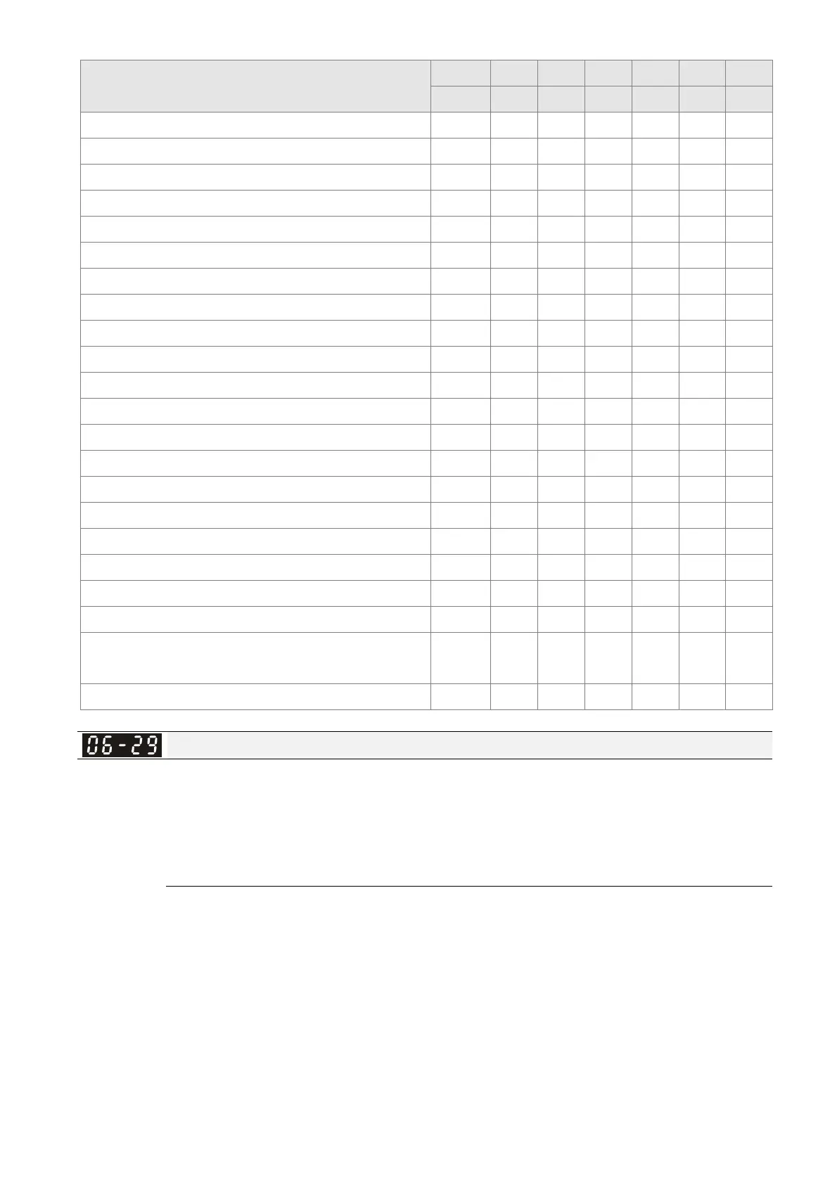
Fault Code
bit 0 bit 1 bit 2 bit 3 bit 4 bit 5 bit 6
current Volt. OL SYS FBK EXI CE
56: Communication error (CE3)
●
57: Communication error (CE4)
●
58: Communication time-out (CE10)
●
61: Y-connection/∆-connection switch error (ydc)
●
62: Deceleration Energy Backup Error (dEb)
●
72: Channel 1 (S1–DCM) safety loop error (STL1)
●
76: Safe Torque Off (STo)
●
77: Channel 2 (S2–DCM) safety loop error (STL2)
●
78: Internal loop error (STL3)
●
79: U-phase over-current before run (Uoc)
●
80: V-phase over-current before run (Voc)
●
81: W-phase over-current before run (Woc)
●
82: U-phase output phase loss (OPHL)
●
83: V-phase output phase loss (OPHL)
●
84: W-phase output phase loss (OPHL)
●
87: Drive overload in low frequency (oL3)
●
89: Initial rotor position detection error (RoPd)
●
140: GFF detected when power on (Hd6)
●
141: GFF before run (BGFF)
●
142: Auto-tuning error 1 (DC test stage) (AUE1)
●
143: Auto-tuning error 2 (High frequency test stage)
(AUE2)
●
144: Auto-tuning error 3 (Rotary test stage) (AUE3)
●
PTC Detection Selection
Default: 0
Settings 0: Warn and continue operation
1: Warn and ramp to stop
2: Warn and coast to stop
3: No warning
Sets the operation mode of a drive after you set Pr.06-29 to define PTC detection.
Running a motor at low frequency for a long time reduces the cooling function of the motor fan. To
prevent the motor from damage due to overheating, use a Positive Temperature Coefficient
thermistor on the motor, and connect the thermistor output signal to the drive’s analog input
terminals.