Chapter 6 Control TerminalsME300
6-4
Terminals Terminal Function Description
RA
Multi-function relay output 1
(Relay N.O. a)
Programmable relay output, see Pr.02-13.
Resistive Load
3 A (N.O.)/3 A (N.C.) 250 V
AC
5 A (N.O.)/3 A (N.C.) 30 V
DC
Inductive Load (COS 0.4)
1.2 A (N.O.)/1.2 A (N.C.) 250 V
AC
2.0 A (N.O.)/1.2 A (N.C.) 30 V
DC
Various kinds of monitor signals output, e.g.: operation,
frequency reached, overload indication etc.
RB
Multi-function relay output 1
(Relay N.C. b)
RC
Multi-function relay common
(Relay)
+10 V Potentiometer power supply
+10.5±0.5 V
DC
/20 mA
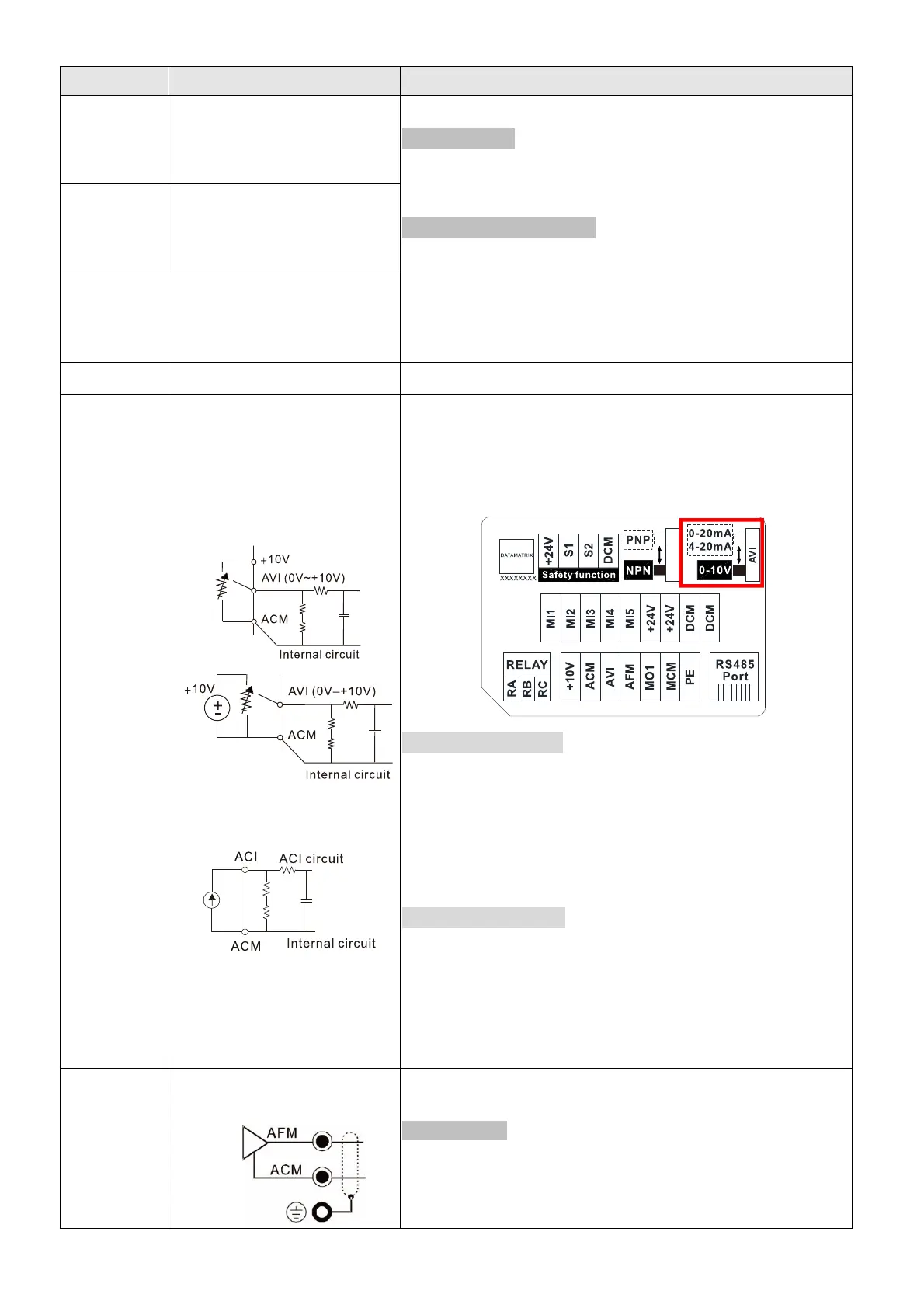
AVI
Analog voltage input
Analog current input
The AVI terminal default voltage mode is set to 0–10 V. To
use the current mode, the AVI must be switched to the
current mode position (0–20 mA/4–20 mA), as the red
frame below shows, and then set Pr.03-28.
Voltage (AVI) mode
Programmable analog input, see Pr.03-00.
Impedance: 20 kΩ
Range 0–Max. Output Frequency (Pr.01-00):
0 to 10 V/-10 to 10 V
Range switching according to Pr.03-00, Pr.03-28.
Current (ACI) mode
Programmable analog input, see Pr.03-01.
Impedance: 250 Ω
Range 0– Maximum Output Frequency (Pr.01-00):
0–20 mA/4–20 mA/0–10 V
Range switching according to Pr.03-01, Pr.03-28.
AFM
Multi-function analog voltage
output
Switch:
The AFM default is 0–10 V (voltage mode).
Voltage mode
Range: 0–10 V (Pr.03-31=0) corresponding to the
maximum operating range of the control object
Maximum output current: 2 mA. Maximum Load: 5 kΩ