D1000 Installation and Service Manual 12
Home LAB-110073 Rev. 3
RANGE ELEMENT DISCONNECT INSTALLATION
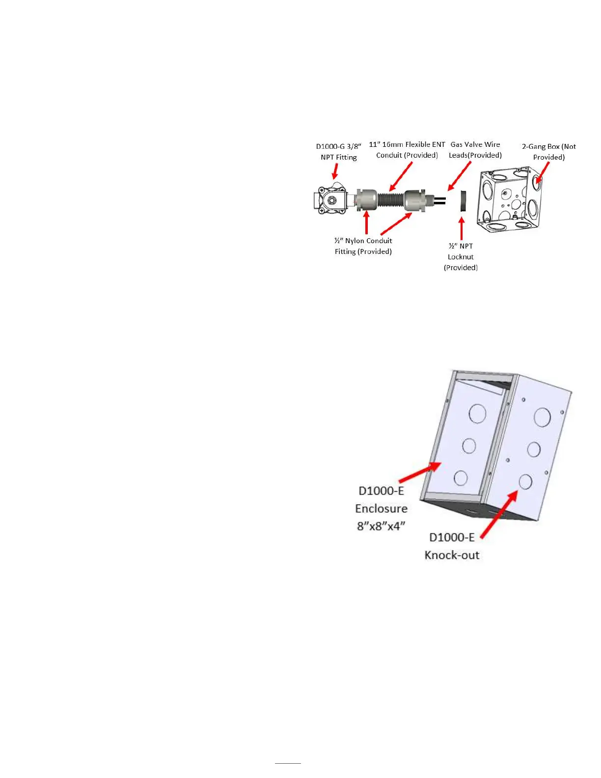
D1000-G Installation
1. Secure the gas line input and output to the D1000-G.
The fittings are 3/8” NPT. Note the direction of the flow,
there is an arrow on the bottom of the D1000-G.
2. The D1000-G has an 11” 16mm Flexible ENT Conduit
with the wire leads inside. Install the 11” 16mm Flexible
ENT Conduit attached with a plug into the 2-Gang Box.
Secure the Box.
3. Run the120 VAC 8 ft 14/2 MC Wire (Provided) from the
hood’s junction box location found on the mounting
bracket, to the power disconnect location.
4. Install the cover for the 2-Gang Box.
Note: The Coil voltage cannot be used to power the
electronics in the range (clock, ignitors, etc.). Doing this voids the warranty and ETL listing of the Hood, in addition to blowing
the fuses and damaging the PLC.
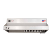
D1000-E Installation
1. Cut a hole in the drywall for the D1000-E Enclosure; refer to the
specification sheets for the dimensions. Be sure to note the 1 ¼”
overhang on both sides of the face plate. The cutout opening
should be about 8 3/8”. The power disconnect has been designed
to fit a standard 2” x 4” framed wall.
5. Run the120 VAC 8 ft 14/2 MC Wire (Provided) from the hood’s
junction box location found on the mounting bracket, to the power
disconnect location.
2. Run 120 VAC 15 – 20 Amps or 220 VAC 20 – 50 Amps from Main
Breaker Panel (Not Provided) to the contactor. This will provide
power to the receptacle.
3. Secure the face plate to the power disconnect.