D1000 Installation and Service Manual 18
Home LAB-110073 Rev. 3
FIRE ALARM CONNECTIONS
The D1000 has three fire alarm connections (discrete switches), each independent from each other. Two are controlled by
the PLC and one is mechanical.
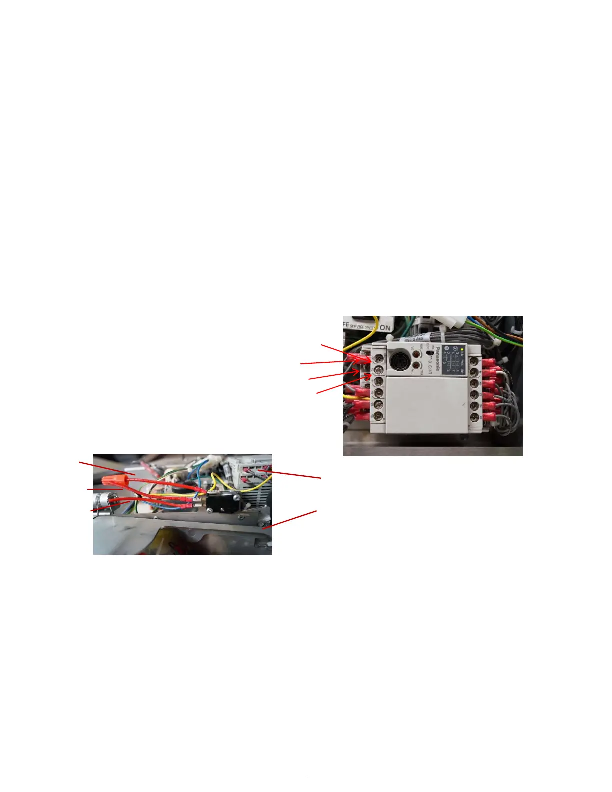
A connection is made to one output (Y#) and one common (C#) at the PLC. The output labeled YO is triggered by
a fault from Hi-Temp, 190F, pressure switch or hose switch. A buzzer in the unit will sound and the power
disconnect will turn off.
Output, Y1, is triggered by a high temperature switch, 190F, and a low-pressure fault in the extinguisher tank
(the fire suppressant has discharged). When there is a fault, a buzzer in the unit will sound and the power
disconnect will turn off.
PLC CONTROLLED ALARMS-REQUIRE POWER TO THE HOOD
Local Alarm Connection: Connect to output Y0 and common C0
Remote Alarm Connection: Connect to output Y1 and common C1
To connect to the alarms, it is recommended that you use a 3.22mm spade fork connector (not supplied), however a
stripped wire is acceptable.
Either one of the connections may be used depending on the needs of the job site.
Connecting the alarm system in configurations described above results in a normally open connection.
Common
Normally Open
Normally Closed
Fire Alarm Switch
Figure 14.2
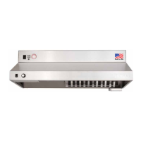
MECHANICAL SWITCH – NOT POWERED
This connection does not require power to be supplied to the hood in order to function. The alarm switch is located above
the actuator arm, next to the PLC assembly. The alarm switch is tripped when the actuator arm is released.
Wire the alarm to the common connector and normally open, or normally closed connection as shown, depending
on what the on-site alarm requires.
Actuator Arm
PLC Assembly
Y0
C0
C1
Y1