D1000 Installation and Service Manual 27
Home LAB-110073 Rev. 3
TROUBLESHOOTING THE D1000 SYSTEM
D1000 OPERATING SYSTEM-PLC DRIVE FUNCTIONS
PROGRAMMABLE LOGIC CONTROLLER (PLC)
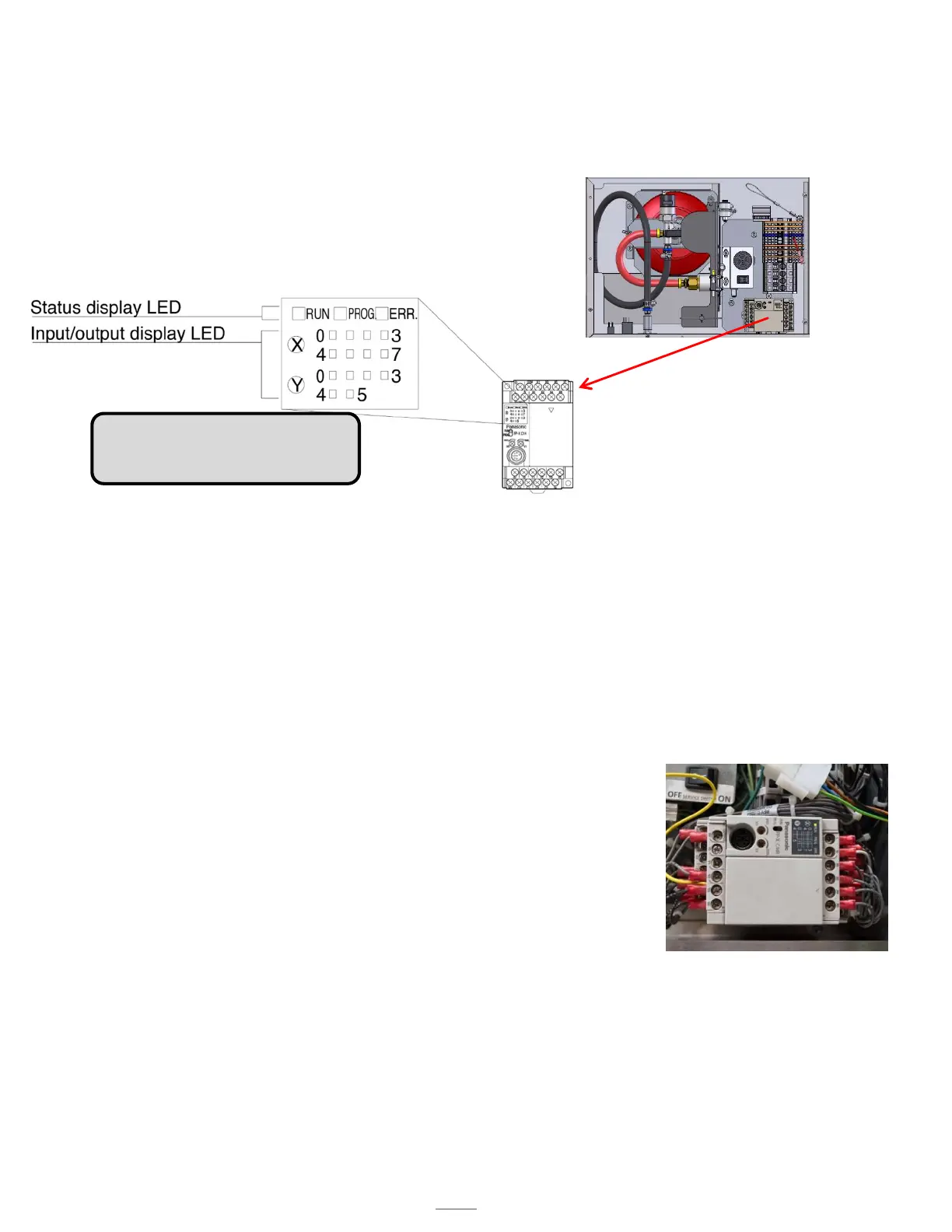
LED Indicators
NOTE: See pages19-20 for the
wiring diagram and schematic table.
HOW THE ENVIRONMENTAL MONITORING SYSTEM WORKS
The PLC operating system is designed to enhance the functionality of the unit and the safety of the cooking environment.
The system relies on the input of a set of three thermostats to control the fan and shutoff power to the range when the
temperature reaches the preset points. There are two temperature thresholds that the PLC responds to: 150◦F and 190◦F.
There are two 150◦F temperature switches. When this set point is reached, the following will occur:
o The fan will turn ON to the ‘HIGH’ speed setting, overriding front panel switch settings.
There is one 190◦F temperature switch. When this set point is reached, the following will occur:
o Power Source Disconnect de-energizes shutting OFF the power to the range.
o ‘Local’ alarm output tripped, indicating a trouble condition with the unit.
The output is from contacts C0 and Y0 on the PLC
The Buzzer beeps five (5x) times
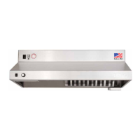
PROGRAMMABLE LOGIC CONTROLLER (PLC)
There are two rows of LED’s next to the X (inputs)
X0 - Hose switch (hose in place) LED ON
X1 - Reset switch (this is ON when the reset switch is pressed)
X2 - Pressure switch (proper pressure) LED ON
X3 - Maintenance switch is in the OFF position for normal operating mode
Note: The maintenance switch is not illuminated in normal operating mode. In
maintenance mode the maintenance switch is illuminated.
X4 -Both low temperature thermostats are in the normal position LED ON
X6 - High temperature thermostat in the normal position LED ON
There are two rows of LED’s next to the Y (outputs)
Y0 - Alarm output for local alarm is off unless one of the following events occurs. The hose switch, the high
temperature switch, or the pressure switch open due to an event.
Y1 - Alarm output is off unless the tank’s pressure drops below 75 PSI and the high temperature thermostat is above 190◦F.
The output turns on only if both conditions happen.
Y2 - Status LED (should be off under normal operating conditions)
Y3 - Fan (this will be on when the PLC turns the fan ON)
Y4 - Output to the power disconnect (ON in normal operating conditions) LED ON
Y5 - Output for the buzzer (OFF under normal operating conditions)