D1000 Installation and Service Manual 21
Home LAB-110073 Rev. 3
DUCTING AND AIRFLOW
The ductwork and fittings used for outside venting must be carefully selected to ensure that the static pressure is in line
with the fan parameters. The ducting is provided by other and should be specified by the HVAC contractor on the job as
each local code requirement may differ.
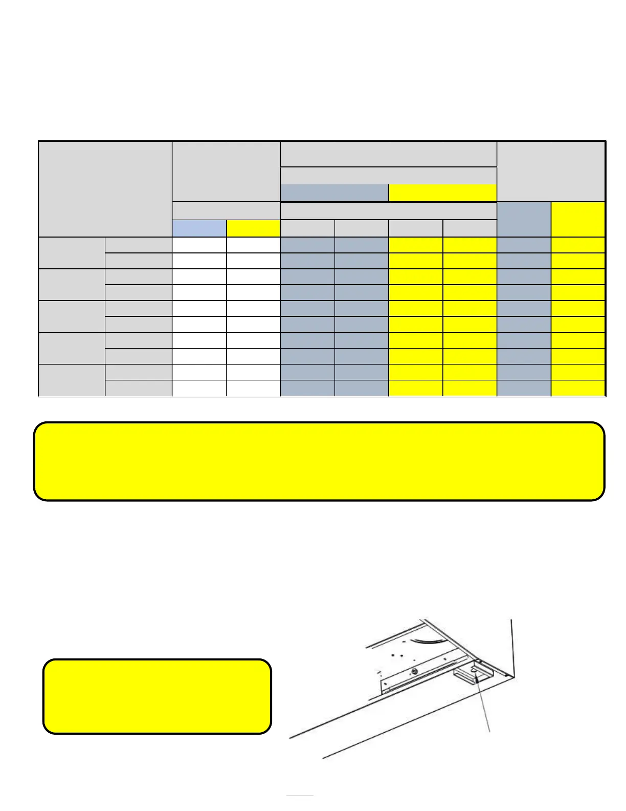
The recommended duct length for all “D” models, allows for up to three 90 angles. The table below are readings tested
at 25’ of duct work where applicable.
STATIC PRESSURE TESTING
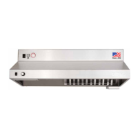
The magnehelic gauge test port opening is located beneath the grease tray. The static pressure needs to be measured to
ensure air flows meet design criteria. The airflow is measured by attaching the gauge tubing to the magnehelic gauge
inlet, and the hood fitting is attached to the grease drain hole beneath the grease tray.
Refer to chart above to meet design standards. This reading will correspond to the static pressures of the ductwork, hood
and fan combination.
Low High Without With Without With
Standard 62 70 -0.01 -0.09 -0.02 -0.18 174 276
NFPA 60 84 -0.04 -0.26 -0.23 -1.38 216 514
Standard 62 70 -0.01 -0.09 -0.01 -0.17 139 279
NFPA 60 80 -0.03 -0.25 -0.17 -1.35 174 519
Standard 57 69 -0.03 -0.23 -0.11 -0.61 283 474
NFPA 60 70 -0.05 -0.29 -0.20 -0.89 297 545
Standard 56 60 -0.02 -0.14 -0.05 -0.28 208 281
NFPA 60 75 -0.01 -0.10 -0.11 -0.66 172 522
Standard 61 73 -0.07 -0.40 -0.14 -0.84 357 499
NFPA 63 75 -0.08 -0.39 -0.22 -1.09 326 548
CFM
(+ - 2.5%)
Low High
Fan Speed
Grease Filter
Front
Rear
In-line
Wall Mount
Roof Mount
dB's
PRESSURE (InWater)
Fan Speed
Low High
Figure 14.12 Magnehelic
Gauge Test Port
WARNING: The static pressure must be
maintained in order for the hood to perform
properly. The grease filter must be in place
when performing the reading.
WARNING: The amount of fittings and ductwork directly a
ects the resistance or static pressure placed on the system. If
the system is not within the proper static pressure range, the heat sensors and controls will be adversely a
ected and will
impact the proper functioning of the safety controls. Therefore it is required that air flow testing be recorded along with
install documentation. The air testing area is accessed by the removal of the grease tray and measured with an air flow
pressure gauge.