D1000 Installation and Service Manual 19
Home LAB-110073 Rev. 3
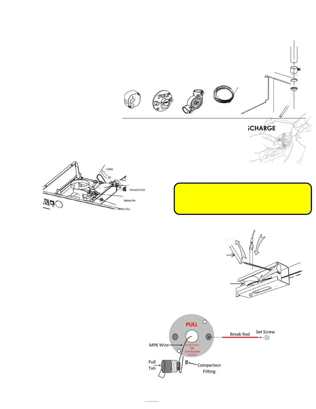
MANUAL PULL STATION (MPK) INSTALLATION
STEP 1: INSTALLING CONDUIT
Mount the pull box in an appropriate location according to local building codes. The MPK supplied with
twenty-five feet of wire rope cable and three elbow pulleys as our listing requires.
Install ½” conduit (not provided) between the unit and the pull box, using the pulleys as
needed.
Pull the wire rope cable through the conduit and allow 8-12” of slack to be left at the hood unit
end.
Be sure to abide by all local building and fire codes when installing the conduit.
STEP 2: PLACE UNIT IN MAINTENANCE MODE TO HELP PREVENT ACCIDENTAL DISCHARGE
Ensure that the unit is in Maintenance mode (see Page 20).
CHECK THE FOLLOWING:
The safety pin is in its slot at the top of the extinguisher tank. See figure 14.3 Tank Safety
Pin
The safety key is in its slot in the actuator arm.
STEP 3: INSTALL ACTUATION CABLE AND PIN TO CLEVIS
Thread the actuation cable through the conduit, with the pin reaching the unit.
Remove the grease baffle.
There is a turnbuckle attached to the link cable, located in the plenum. Turn the
turnbuckle to release tension on the link cable
In the upper corner, locate the two pulleys (see Figure 14.4 Pulley-Unit)
Hold the rear-most pulley in place.
From the top of the unit, replace the existing clevis pin with the one on the wire rope cable.
Push the pin through the pulley until it clicks in place.
Re-attach the actuation cable onto the actuator arm.
STEP 4: INSTALL WIRE ROPE CABLE TO PULL FACE
While the unit is still in Maintenance position, attach the wire rope cable to the pull
face by crimping a sleeve in the wire rope cable through the back side of the handle.
Ensure the wire rope cable is securely crimped
to withstand at least 40 lbs. of pull force.
Leave no more than 12” of slack in the line on
the pull face end but maintain 8-12” of slack.
Remove the MPK handle by loosening the set
screw in one of the studs and sliding the red
plastic rod out.
Attach the pull face to the pull box that is
already mounted to the wall, collecting any
slack into the pull box.
Pull Box (X1)
Pull Face (X1)
Elbow Pulley (X3)
Wire Rope Cable
crimped with sleeve
and Pin (25ft)
Figure 14.3
Tank Safety Pin
WARNING: You must allow for 8-12” of slack in the
wire rope cable to sit at the pull face. Failure to do so
will cause the unit to discharge the next time the unit is
lowered into its service position.
Conduit Attachment
mounting bracket
Figure 14.4
Pulley-Unit
Clevis Pin
Rear most
Pulley