


R
Rebecca JohnsonJul 26, 2025
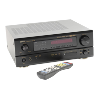
Why is my Denon AVR-1507 display lit but no sound is produced?
- JJudith GarciaJul 26, 2025
If your Denon Stereo Receiver display is lit but no sound is being produced, several factors could be at play. First, make sure the speaker cables are securely connected. Second, ensure the INPUT SELECTOR knob is in the correct position. Third, check that the volume control is not set to the minimum; turn it up to a suitable level. Also, verify that MUTING is switched off. Finally, if you're using a digital signal, ensure a digital signal input source is properly selected.