EasyManua.ls Logo

Denon AVR-1912E3

Denon AVR-1912E3
196 pages
To Next Page IconTo Next Page
Loading...
START::|qzT7t3cIXfGvpSN6RPbAWw==|1Ai2yjCFMIEeNAMN4o8xACrfn0dvKIUUVX0LLQXbRM8=|RtRIz5LbaS+BXuKmvA5tJg==|::END
D&M Holdings Inc.
SERVICE MANUAL
e
e
Copyright 2012 D&M Holdings Inc. All rights reserved.
WARNING: Violators will be prosecuted to the maximum extent possible.
MODEL JP E3 E2 EK EA E1 E1K E1C
AVR-1912
P P P P
AVR-2112CI
P
INTEGRATED NETWORK AV RECEIVER
s
s
s
s
Ver. 6
S0436-0V06DM/DG1202
Some illustrations using in this service manual are slightly different from the actual set.
Please use this service manual with referring to the operating instructions without fail.
• For purposes of improvement, specications and design are subject to change without notice.
Please refer to the
MODIFICATION NOTICE.

Table of Contents

Question and Answer IconNeed help?

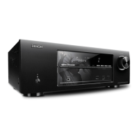
Do you have a question about the Denon AVR-1912E3 and is the answer not in the manual?

Denon AVR-1912E3 Specifications

General IconGeneral
BrandDenon
ModelAVR-1912E3
CategoryReceiver
LanguageEnglish

Summary

SAFETY PRECAUTIONS

LEAKAGE CURRENT CHECK

Procedure for checking leakage current before returning the set to the customer.

CAUTIONS IN SERVICING

General cautions and instructions to heed during servicing and inspection.

IMPORTANT SAFETY PARTS

Details on safety properties of parts and the need to use designated parts.

TECHNICAL SPECIFICATIONS

Audio Section

Details on power amplifier, analog input, frequency response, and S/N ratio.

Video Section

Standard video connectors, input/output levels, and frequency response.

Tuner Section

FM/AM receiving range, sensitivity, quieting sensitivity, and harmonic distortion.

General

Power supply, power consumption, and external dimensions for various models.

DIMENSION

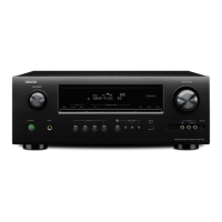
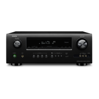
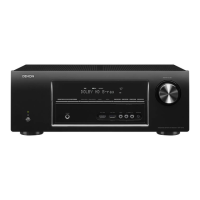
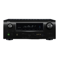
Mechanical dimensions for AVR-1912E3 and other models, including diagrams.

CAUTIONS IN SERVICING

Initializing INTEGRATED NETWORK AV RECEIVER

Procedure to initialize the unit when μcom or Digital P.W.B. is replaced.

Service Jig

Jigs required for servicing, including extension cable kit and writing kit.

DISASSEMBLY

SPECIAL MODE

Special mode setting button (for 1912 E3 model)

Details on special modes accessible via front panel buttons for the 1912E3 model.

Special mode setting button (for AVR-1912 E2 EAE1 C,2112 CIE3 model)

Details on special modes accessible via front panel buttons for other models.

BLOCK DIAGRAM

JIG FOR SERVICING

Connection of PCB HDMI JIG

Procedures for connecting the PCB HDMI JIG for servicing.

WHEN THE MICROPROCESSOR IS REPLACED WITH A NEW ONE

PROCEDURE FOR UPGRADING THE VERSION OF THE FIRMWARE

ADJUSTMENT

Audio Section

Procedure for adjusting the idling current in the audio section.

SURROUND MODES AND PARAMETERS

TROUBLE SHOOTING

POWER

Troubleshooting steps for power-related issues, including no power or flashing indicator.

Analog video

Troubleshooting steps for issues with analog video output (CVBS/S/COMPONENT).

HDMIDVI

Troubleshooting steps for no picture or sound output via HDMI/DVI connection.

SEMICONDUCTORS

ICs

Details on major ICs used, including pin functions and block diagrams.

Related product manuals