EasyManua.ls Logo

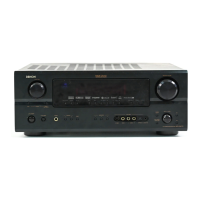
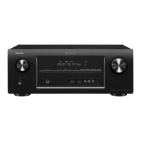
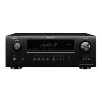
Denon AVR-2307 User Manual

Denon AVR-2307
117 pages
To Next Page IconTo Next Page
Page #1 background imageLoading...
Page #1 background image
SERVICE MANUAL
MODEL
AVR-2307CI
AVR-2307
AVC-1930
AVR-887
AV SURROUND RECEIVER
AV SURROUND AMPLIFIER
For U.S.A.,Canada,Europe,
Asia,Taiwan R.O.C.,China
& Japan model
TOKYO, JAPAN
X0305 V.08 DE/CDM 0707
Some illustrations using in this service manual are
slightly different from the actual set.
Please use this service manual with referring to the
operating instructions without fail.
For purposes of improvement, specifications and
design are subject to change without notice.
本文中に使用しているイラストは、説明の都合上現物
と多少異なる場合があります。
修理の際は、必ず取扱説明書を参照の上、作業を行っ
てください。
サービスをおこなう前に、このサービスマニュアルを
必ずお読みください。本機は、火災、感電、けがなど
に対する安全性を確保するために、さまざまな配慮を
おこなっており、また法的には「電気用品安全法」に
もとづき、所定の許可を得て製造されております。
従ってサービスをおこなう際は、これらの安全性が維
持されるよう、このサービスマニュアルに記載されて
いる注意事項を必ずお守りください。
本機の仕様は性能改良のため、予告なく変更すること
があります。
補修用性能部品の保有期間は、製造打切後8年です。
注 意
Denon Brand Company, D&M Holdings Inc.
Please refer to the
MODIFICATION NOTICE.
Ver. 8
Question and Answer IconNeed help?

Do you have a question about the Denon AVR-2307 and is the answer not in the manual?

Denon AVR-2307 Specifications

General IconGeneral
BrandDenon
ModelAVR-2307
CategoryReceiver
LanguageEnglish

Summary

SERVICE MANUAL

CAUTION

Important safety precautions before performing service.

SAFETY PRECAUTIONS

LEAKAGE CURRENT CHECK

Procedure to check leakage current before returning unit to customer.

Electric Shock Precautions

Warnings and precautions regarding electric shock hazards during servicing.

Parts Handling and Safety

Precautions for safe disassembly, assembly, and using designated parts.

Post-Servicing Safety Inspection

Ensuring safety after servicing, including insulation checks.

DIMENSION DIAGRAMS

CAUTION IN SERVICING

AV Receiver Initialization Procedure

Procedure for initializing the AV surround receiver after component replacement.

ADJUSTMENT PROCEDURES

Audio Section Adjustments

Adjustment procedures for the audio section.

Idling Current Adjustment

Procedure for adjusting the idling current of audio circuits.

VIDEO SECTION PROCEDURES

Video Section Setting and Preparation

Setting up equipment and preparing for video section adjustments.

DVD Player Setup for Adjustment

DVD player setup and output confirmation for video adjustment.

VIDEO SIGNAL ADJUSTMENT PROCEDURE

S MONITOR OUT Signal Adjustment

Adjusting S MONITOR OUT signal levels using oscilloscope waveform.

COMPONENT OUT Signal Adjustment

Adjusting COMPONENT OUT signal levels using oscilloscope waveform.

HDMI UNIT SPECIFICATIONS

AUDIO BLOCK DIAGRAM (1/3)

VIDEO BLOCK DIAGRAM (2/3)

POWER BLOCK DIAGRAM (3/3)

LEVEL DIAGRAMS (1/2)

LEVEL DIAGRAMS (2/2)

SEMICONDUCTOR DATASHEETS

M30626 CPU IC Pin Assignment

Pin assignment and terminal function for M30626 CPU.

SEMICONDUCTOR DATASHEETS (Continued)

M30626 CPU Terminal Functions

Detailed pin functions for M30626 CPU.

SEMICONDUCTOR DATASHEETS (Continued)

M30626 CPU Terminal Functions Continued

Continued terminal functions for M30626 CPU.

BU4094 IC Pin Assignments

BU4094 IC551 MUTE Control Functions

Pin assignment and function for BU4094 IC551 (MUTE Control).

BU4094 IC552 RELAY Control Functions

Pin assignment and function for BU4094 IC552 (RELAY Control).

BU4094 IC553 MUTE&RELAY Control Functions

Pin assignment and function for BU4094 IC553 (MUTE&RELAY Control).

INTEGRATED CIRCUIT DATASHEETS

CXA1511M-T4 IC Specifications

Block diagram and pin configuration for CXA1511M-T4.

TC74VHC Series IC Pin Assignments

Pin assignments for TC74VHCU04F, TC74VHC14F, TC74VHCT08AFT ICs.

INTEGRATED CIRCUIT DATASHEETS (Continued)

MM74HC4053SJ Video IC Truth Table

Truth table for MM74HC4053SJ S-C VIDEO IC.

BU4094BCFV Video IC Pin Assignments

Pin assignment of video extended IC BU4094BCFV.

INTEGRATED CIRCUIT DATASHEETS (Continued)

M35015-SP S-C VIDEO IC Block Diagram

Block diagram and pin function for M35015-SP S-C VIDEO IC.

INTEGRATED CIRCUIT DATASHEETS (Continued)

NJM2229M S-C VIDEO IC Block Diagram

Block diagram for NJM2229M S-C VIDEO IC.

NJW1321FP1 COMPO IC Pin Assignment

Pin assignment for NJW1321FP1 COMPO IC.

NJM2581M COMPO IC Pin Assignment

Pin assignment for NJM2581M COMPO IC.

INTEGRATED CIRCUIT DATASHEETS (Continued)

M30620FCPGP HDMI IC Terminal Functions

Terminal function for M30620FCPGP HDMI IC.

INTEGRATED CIRCUIT DATASHEETS (Continued)

M30620FCPGP HDMI IC Terminal Functions Continued

Continued terminal functions for M30620FCPGP HDMI IC.

INTEGRATED CIRCUIT DATASHEETS (Continued)

AS7C340096 HDMI IC Details

Top view and pin assignment for AS7C340096A-10TCN HDMI IC.

BA4510F HDMI IC Function Table

Function table for BA4510F-E2 HDMI IC.

INTEGRATED CIRCUIT DATASHEETS (Continued)

ADSP21266 HDMI IC Details

Top view and terminal function for ADSP21266SKSTZ-2B-EC HDMI IC.

INTEGRATED CIRCUIT DATASHEETS (Continued)

LC89057W HDMI IC Details

Block diagram and terminal function for LC89057W HDMI IC.

INTEGRATED CIRCUIT DATASHEETS (Continued)

SN74LV573APWR HDMI IC Function Table

Function table for SN74LV573APWR HDMI IC.

SN74LVC139APWR HDMI IC Function Table

Function table for SN74LVC139APWR HDMI IC.

INTEGRATED CIRCUIT DATASHEETS (Continued)

ADAU1328BSTZ HDMI IC Terminal Functions

Terminal function for ADAU1328BSTZ HDMI IC.

INTEGRATED CIRCUIT DATASHEETS (Continued)

BR24L02F HDMI IC Block Diagram

Block diagram and pin configuration for BR24L02F-W HDMI IC.

INTEGRATED CIRCUIT DATASHEETS (Continued)

SiI9030CTU HDMI IC Block Diagram

Functional block diagram for SiI9030CTU-7 HDMI IC.

INTEGRATED CIRCUIT DATASHEETS (Continued)

ADV7320 HDMI IC Pin Descriptions

Table of pin function descriptions for ADV7320 HDMI IC.

INTEGRATED CIRCUIT DATASHEETS (Continued)

BH7868FS HDMI IC Block Diagram

Block diagram for BH7868FS HDMI IC.

AK4385 HDMI IC Block Diagram

Block diagram for AK4385 HDMI IC.

INTEGRATED CIRCUIT DATASHEETS (Continued)

LTC4300-2CMS8 HDMI IC Block Diagram

Block diagram for LTC4300-2CMS8 HDMI IC.

FRONT PANEL DISPLAY

FL Display Pin Connections and Grid Assignment

Pin connection and grid assignment for FL display.

FRONT PANEL DISPLAY TIMING

FL Display Anode Timing Charts

Timing charts for anode segments and connections of the FL display.

PRINTED WIRING BOARD LAYOUTS

MAIN UNIT PWB - Component Side

Component side layout of the main unit printed wiring board.

PRINTED WIRING BOARD LAYOUTS (Continued)

MAIN UNIT PWB - Foil Side

Foil side layout of the main unit printed wiring board.

PRINTED WIRING BOARD LAYOUTS (Continued)

CPU UNIT PWB - Component Side

Component side layout of the CPU unit printed wiring board.

PRINTED WIRING BOARD LAYOUTS (Continued)

CPU UNIT PWB - Foil Side

Foil side layout of the CPU unit printed wiring board.

PRINTED WIRING BOARD LAYOUTS (Continued)

CNT UNIT PWB - Component Side

Component side layout of the CNT unit printed wiring board.

PRINTED WIRING BOARD LAYOUTS (Continued)

CNT UNIT PWB - Foil Side

Foil side layout of the CNT unit printed wiring board.

PRINTED WIRING BOARD LAYOUTS (Continued)

OPTICAL UNIT PWB - Component Side

Component side layout of the optical unit printed wiring board.

PRINTED WIRING BOARD LAYOUTS (Continued)

OPTICAL UNIT PWB - Foil Side

Foil side layout of the optical unit printed wiring board.

PRINTED WIRING BOARD LAYOUTS (Continued)

2CH-AMP UNIT PWB Layouts

Component side layout of the 2CH-AMP unit printed wiring board.

PRINTED WIRING BOARD LAYOUTS (Continued)

INPUT UNIT PWB (1/2)

Component side layout of the input unit printed wiring board.

PRINTED WIRING BOARD LAYOUTS (Continued)

INPUT UNIT PWB (2/2)

Foil side layout of the input unit printed wiring board.

PRINTED WIRING BOARD LAYOUTS (Continued)

S-C VIDEO UNIT PWB Layouts

Component and foil side layouts of the S-C VIDEO unit.

PRINTED WIRING BOARD LAYOUTS (Continued)

COMPONENT UNIT PWB Layouts

Component and foil side layouts of the COMPONENT unit.

PRINTED WIRING BOARD LAYOUTS (Continued)

HDMI UNIT PWB (1/2)

Component side layout of the HDMI unit printed wiring board.

PRINTED WIRING BOARD LAYOUTS (Continued)

HDMI UNIT PWB (2/2)

Foil side layout of the HDMI unit printed wiring board.

PRINTED WIRING BOARD LAYOUTS (Continued)

D-VIDEOI UNIT PWB Layouts

Component and foil side layouts of the D-VIDEOI unit.

PARTS LIST NOTES

Resistor Notation Explanation

Explanation of resistor part number notation and symbols.

Capacitor Notation Explanation

Explanation of capacitor part number notation and symbols.

Parts List Ordering Information

Notes regarding parts list ordering and usage.

MAIN PWB Unit Parts List

Semiconductors Group

List of semiconductors used in the MAIN P.W.B. ASSY.

MAIN PWB Unit Parts List (Continued)

Resistors Group

List of resistors used in the MAIN P.W.B. ASSY.

MAIN PWB Unit Parts List (Continued)

Capacitors Group

List of capacitors used in the MAIN P.W.B. ASSY.

MAIN PWB Unit Parts List (Continued)

Others Parts Group

List of other parts (connectors, fuses) for MAIN P.W.B. ASSY.

MAIN PWB Unit Parts List (Continued)

Others Parts Group (Continued)

Continued list of other parts for MAIN P.W.B. ASSY.

CPU PWB Unit Parts List

Semiconductors Group

List of semiconductors for the CPU P.W.B. UNIT ASSY.

CPU PWB Unit Parts List (Continued)

Resistors Group

List of resistors for the CPU P.W.B. UNIT ASSY.

CPU PWB Unit Parts List (Continued)

Capacitors Group

List of capacitors for the CPU P.W.B. UNIT ASSY.

CNT PWB Unit Parts List

Semiconductors Group

List of semiconductors for the CNT P.W.B. UNIT ASSY.

CNT PWB Unit Parts List (Continued)

Resistors Group

List of resistors for the CNT P.W.B. UNIT ASSY.

CNT PWB Unit Parts List (Continued)

Capacitors Group

List of capacitors for the CNT P.W.B. UNIT ASSY.

CNT PWB Unit Parts List (Continued)

Others Parts Group

List of other parts (connectors, fuses) for CNT P.W.B. UNIT ASSY.

OPTICAL PWB Unit Parts List

Semiconductors Group

List of semiconductors for the OPTICAL P.W.B. UNIT ASSY.

OPTICAL PWB Unit Parts List (Continued)

Capacitors Group

List of capacitors for the OPTICAL P.W.B. UNIT ASSY.

OPTICAL PWB Unit Parts List (Continued)

Others Parts Group

List of other parts (connectors, fuses) for OPTICAL P.W.B. UNIT ASSY.

2CH-AMP PWB Unit Parts List

Semiconductors Group

List of semiconductors for the 2CH-AMP P.W.B. UNIT ASSY.

2CH-AMP PWB Unit Parts List (Continued)

Capacitors Group

List of capacitors for the 2CH-AMP P.W.B. UNIT ASSY.

INPUT PWB Unit Parts List

Semiconductors Group

List of semiconductors for the INPUT P.W.B. UNIT ASSY.

INPUT PWB Unit Parts List (Continued)

Capacitors Group

List of capacitors for the INPUT P.W.B. UNIT ASSY.

INPUT PWB Unit Parts List (Continued)

Capacitors Group (Continued)

Continued list of capacitors for INPUT P.W.B. UNIT ASSY.

INPUT PWB Unit Parts List (Continued)

Others Parts Group

List of other parts (connectors, fuses) for INPUT P.W.B. UNIT ASSY.

S-C VIDEO PWB Unit Parts List

Semiconductors Group

List of semiconductors for the S-C VIDEO P.W.B. UNIT ASSY.

S-C VIDEO PWB Unit Parts List (Continued)

Capacitors Group

List of capacitors for the S-C VIDEO P.W.B. UNIT ASSY.

COMPONENT PWB Unit Parts List

Semiconductors Group

List of semiconductors for the COMPONENT P.W.B. UNIT ASSY.

COMPONENT PWB Unit Parts List (Continued)

Capacitors Group

List of capacitors for the COMPONENT P.W.B. UNIT ASSY.

HDMI PWB Unit Parts List

Semiconductors Group

List of semiconductors for the HDMI P.W.B. UNIT ASSY.

HDMI PWB Unit Parts List (Continued)

Capacitors Group

List of capacitors for the HDMI P.W.B. UNIT ASSY.

HDMI PWB Unit Parts List (Continued)

Capacitors Group (Continued)

Continued list of capacitors for HDMI P.W.B. UNIT ASSY.

HDMI PWB Unit Parts List (Continued)

Capacitors Group (Continued)

Continued list of capacitors for HDMI P.W.B. UNIT ASSY.

HDMI PWB Unit Parts List (Continued)

Capacitors Group (Continued)

Continued list of capacitors for HDMI P.W.B. UNIT ASSY.

HDMI PWB Unit Parts List (Continued)

Others Parts Group

List of other parts (connectors, fuses) for HDMI P.W.B. UNIT ASSY.

EXPLODED VIEW OF AVR-2307 (Europe & China model)

Critical Parts Warning

Warning about critical parts and using specified replacements.

EXPLODED VIEW PARTS LIST

MAIN P.W.B. UNIT ASSY Parts List

Parts list for the MAIN P.W.B. UNIT ASSY.

EXPLODED VIEW PARTS LIST (Continued)

S-C VIDEO P.W.B. UNIT ASSY Parts List

Parts list for the S-C VIDEO P.W.B. ASSY.

COMPONENT P.W.B. UNIT ASSY Parts List

Parts list for the COMPONENT P.W.B. ASSY.

EXPLODED VIEW PARTS LIST (Continued)

SCREWS List

List of screws used in the assembly.

EXPLODED VIEW PARTS LIST (Continued)

SCREWS List (Continued)

Continued list of screws used in the assembly.

PACKING VIEW

Packing and Accessories List

List of items included in the packing and accessories.

Packing and Accessories Details

Battery, Labels, and Box Details

Details on batteries, various labels, and box markings.

Warranty and Cord Information

Details on warranty cards and cord assemblies.

WIRING DIAGRAM

SCHEMATIC DIAGRAM NOTES

Critical Parts Warning

Warning about critical parts and using specified replacements.

Pre-Return Unit Checks

Cautionary notes on checks before returning the unit to the customer.

Problem Resolution Warning

Warning against returning unit before problem resolution.

Schematic Diagram Notices

Notices regarding resistance, capacitance, measurement conditions, and circuit changes.
Related product manuals