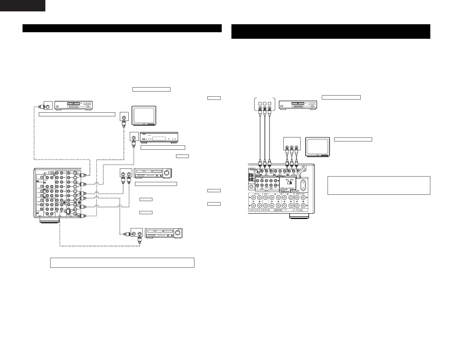
DVD player or video disc player (VDP)
Monitor TV
Video deck 2
Video deck 1
TV or satellite broadcast tuner
Connecting a DVD player or a video disc player (VDP)
Connecting a monitor TV
Connecting the video decks
Connecting a TV or DBS tuner
DVD
• Connect the DVD player’s S-Video output jack to the S-
VIDEO DVD IN jack using an S-Video connection cord.
•A VDP can be connected to the VDP jacks in the same way.
• It is also possible to connect a video disc player, DVD player,
video camcorder, game machine, etc., to the V.AUX jacks.
MONITOR OUT
• Connect the TV’s S video input (S-VIDEO INPUT) to the
MONITOR OUT jack using a S jack connection cord.
S-VIDEO
• Connect the TV’s or DBS tuner’s S video output jack (S-
VIDEO OUTPUT) to the TV or DBS IN jack using
an S-Video connection cord.
S-VIDEO
• Connect the video deck’s S output jack (S-OUT) to the
VCR-1 IN jack and the video deck’s S input jack (S-IN) to the
VCR-1 OUT jack using S-Video connection cords.
• Connect the video deck’s S output jack (S-OUT) to the
VCR-2 IN jack and the video deck’s S input jack (S-IN) to the
VCR-2 OUT jack using S-Video connection cords.
S-VIDEO
S-VIDEO
S-VIDEO
S-VIDEO
Connecting the video components equipped with S-Video jacks
• When making connections, also refer to the operating instructions of the other components.
• A note on the S input jacks
The input selectors for the S inputs and Video inputs work in conjunction with each other.
• Precaution when using S-jacks
This unit’s S-jacks (input and output) and video pin jacks (input and output) have independent circuit
structures, so that video signals input from the S-jacks are only output from the S-jack outputs and video
signals input from the pin jacks are only output from the pin jack outputs.
When connecting this unit with equipment that is equipped with S-jacks, keep the above point in mind and
make connections according to the equipment’s instruction manuals.
DVD player
Monitor TV
Connecting a DVD player
Connecting a monitor TV
DVD IN jacks
• Connect the DVD player’s color difference (component) video output jacks
(COMPONENT VIDEO OUTPUT) to the COMPONENT VIDEO-1 IN jack using 75
Ω/ohms coaxial video pin-plug cords.
• In the same way, another video source with component video outputs such as
a TV or DBS tuner, etc., can be connected to the VIDEO-2 color difference
(component) video jacks.
MONITOR OUT jack
• Connect the TV’s color difference (component)
video input jacks (COMPONENT VIDEO INPUT)
to the COMPONENT MONITOR OUT jack using
75 Ω/ohms coaxial video pin-plug cords.
• The color difference input jacks may be indicated differently on some
TVs, monitors or video components (“CR, CB and Y”, “R-Y, B-Y and Y”,
“Pr, Pb and Y”, etc.). For details, carefully read the operating instructions
included with the TV or other component.
Connecting the Video Components equipped with Color Difference
(Component - Y, P
R
/C
R
, P
B
/C
B
) Video Jacks
• When making connections, also refer to the operating instructions of the other components.
• The signals input to the color difference (component) video jacks are not output to the VIDEO output jack
(yellow) or the S-Video output jack.
• Some video sources with component video outputs are labeled Y, C
B, CR, or Y, Pb, Pr, or Y, R-Y, B-Y. These
terms all refer to component video color difference output.
• The function assigned to the component video input can be changed at the system setup. For details, see
“Setting the Video In Assignment” on page 14.
• The AVR-2803’s on-screen display signals are not output from the color difference (component) video output
jacks (MONITOR OUT).
Connect the components’ audio inputs and outputs as described on page 5.
 Loading...