8
AVR-1910/1620/1610/790/590
DISASSEMBLY
• Disassemble in order of the arrow of the figure of following flow.
• In the case of the re-assembling, assemble it in order of the reverse of the following flow.
• In the case of the re-assembling, observe "attention of assembling" it.
About the photos used for descriptions in the “DISASSEMBLY” section.
• The direction from which the photographs used herein were photographed is indicated at "Direction of photograph: ***" at
the left of the respective photographs.
• Refer to the table below for a description of the direction in which the photos were taken.
• Photographs for which no direction is indicated were taken from above the product.
• The photograph is AVR-1910.
CABINET TOP
PANEL FRONT ASSY PCB CNT1 PCB SPEAKER ASSY
Refer to "DISASSEMBLY 1.PANEL FRONT ASSY" Refer to "DISASSEMBL 2.PCB CNT1" Refer to "DISASSEMBLY 3.PCB SPEAKER ASSY"
and "EXPLODED VIEW" and "EXPLODED VIEW" and "EXPLODED VIEW"
PCB POWER SW ASSY PCB CNT1 (Ref. No. of EXPLODED VIEW : 71) PCB SPEAKER ASSY
(Ref. No. of EXPLODED VIEW : 9) (Ref. No. of EXPLODED VIEW : 63)
PCB FUNC ASSY
(Ref. No. of EXPLODED VIEW : 10)
PCB FRONT ASSY
(Ref. No. of EXPLODED VIEW : 11)
CHASSIS BACK PCB POWER/POWER SUPPLY ASSY
PCB ENCORDER
Refer to "DISASSEMBLY 4.CHASSIS BACK" Refer to "DISASSEMBLY
(Ref. No. of EXPLODED VIEW : 13) and "EXPLODED VIEW" 6.PCB POWER/POWER SUPPLY ASSY"
PCB HEAD PHONE ASSY
and "EXPLODED VIEW"
(Ref. No. of EXPLODED VIEW : 14) PCB POWER SUPPLY ASSY
PCB V-AUX ASSY (Ref. No. of EXPLODED VIEW : 56)
(Ref. No. of EXPLODED VIEW : 21) PCB POWER ASSY
PCB MIC ASSY
PCB MAIN ASS
(Ref. No. of EXPLODED VIEW : 57)
(Ref. No. of EXPLODED VIEW : 22)
Refer to "DISASSEMBLY 5.PCB MAIN ASSY"
PCB CNT ENCORDER and "EXPLODED VIEW"
(Ref. No. of EXPLODED VIEW : 61) PCB MAIN ASSY
TRANS MAIN
PCB SW (Ref. No. of EXPLODED VIEW : 50)
Referto"DISASSEMBLY8.TRANSMAIN"
(Ref. No. of EXPLODED VIEW : 78) PCB INPUT ASSY and "EXPLODED VIEW"
(Ref. No. of EXPLODED VIEW : 51) TRANS MAIN
PCB VIDEO ASSY (Ref. No. of EXPLODED VIEW : 46)
PCB AMP ASSY (Ref. No. of EXPLODED VIEW : 53)
Refer to "DISASSEMBLY 7.PCB AMP ASSY"
PCB DIGITAL ASSY
and "EXPLODED VIEW" (Ref. No. of EXPLODED VIEW : 54)
PCB AMP ASSY PCB HDMI ASSY
(Ref. No. of EXPLODED VIEW : 33) (Ref. No. of EXPLODED VIEW : 55)
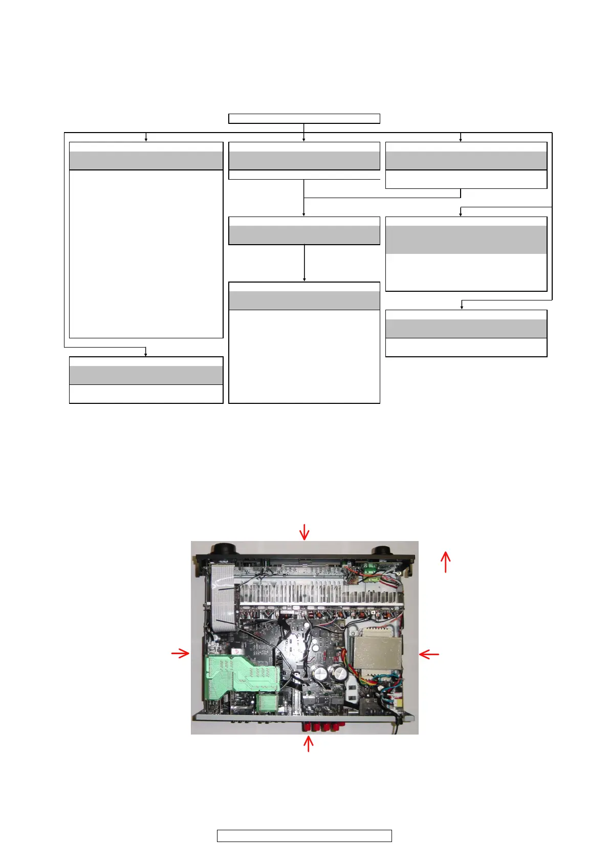
The viewpoint of each photograph
(Photografy direction)
[View from above]
Front side
Direction of photograph: B
Direction of photograph: D
Direction of photograph: C
Direction of photograph: A

 Loading...