Home
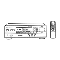
Denon
Stereo Receiver
AVR-900
Denon AVR-900 Service Manual
4
of 1
of 1 rating
50 pages
Give review
Manual
Specs
To Next Page
To Next Page
To Previous Page
To Previous Page
Loading...
SRS
a
eee
AE
-DO
Ee
@
AUDIO
SECTION
Idling
Current
(1U-2865-1)
Required
measurement
equipment:
DC
Voltmeter
Arrangement
(1)
Avoid
direct
blow
from
an
air
conditioner
or
an
electric
fan,
and
adjust
the
unit
at
normal
room
temperature
15°C
~
30°C.
(59°F
~
86°F).
(2)
Presetting
@
POWER
(Power
source
switch)
~
ON
@
MODE
(Mode
buttton)
—
STEREO
@
FUNCTION
(Function
button)
~
CD
@
VOLUME
(Volume
control)
—
0:
fully
counterclockwise
(
(©
min.)
@
BASS,
TREBLE
(Tone
control)
~—
0:
(Controls
to
center)
@
SPEAKERS
(Speaker
terminal
)
—
No
load
(Do
not
connect
speaker,
dummy
resistor,
etc.)
Adjustment
(1)
Remove
top
cover
and
set
VR401,
VR301
and
VR302
of
1U-2865-1
or
1U-2865A-1
(Main
Unit)
at
counterclockwise
fully.
(2)
Connect
DC
Voltmeter
to
test
points
(Lch
T.P.301,
Reh
T.P.302,
CENTER
ch
T.P.401).
(3)
Connect
power
cord
to
AC
Line,
and
turn
power
switch
"ON".
(4)
Allow
15
minutes,
and
tum
VR301,
VR302
and
VR401
clockwise
(
“
)
and
adjust
the
TEST
POINTS
voltage
to
1.5
mV
+0.5
mV
DC.
(5)
After
2
minutes
from
preset,
turn
VR301,
VR302
and
VR401
to
set
the
voltage
to
3
mV
+
0.5mV
DC.
PUNTO.
|
U.S.A.
and
CANADA
1U-2865
EUROPE,
U.K.,
Asia
1U-2865A
1U-2865-1
Main
Unit
(Component
Side)
DC
Voltmeter
1U-2865
TP401
VR401
S
oe
4
TP301
VR301
VR302
TP302
ial
RC)
12
14
Table of Contents
Table of Contents
1
Wire Arrangement
10
Disassembly
11
Connection Diagram of Measuring Instruments
12
Semiconductors
14
Note for Parts List
23
Parts List of P. W. Board
24
Printed Wiring Board
31
Exploded View
36
Parts List of Exploded View
37
Addendum Parts List
37
Block Diagram
38
Wiring Diagram
39
Remote Control Unit (Rc-195)
40
Schematic Diagram
41
4
Based on 1 rating
Ask a question
Give review
Questions and Answers:
Need help?
Do you have a question about the Denon AVR-900 and is the answer not in the manual?
Ask a question
Denon AVR-900 Specifications
General
Input sensitivity
2.5mV (MM), 150mV (line)
Output
150mV (line)
Tuning range
FM
Signal to noise ratio
86dB (MM)
Speaker load impedance
16Ω
Related product manuals
Denon AVR-989
86 pages
Denon AVR-983
76 pages
Denon AVR-991
116 pages
Denon AVR-990
108 pages
Denon AVR-982
128 pages
Denon AVR-2801/981
127 pages
Denon AVR-85
38 pages
Denon AVR-887
82 pages
Denon AVR-786
68 pages
Denon AVR-888
78 pages
Denon AVR-391
111 pages
Denon AVR-591
83 pages