Home
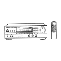
Denon
Stereo Receiver
AVR-900
Denon AVR-900 Service Manual
4
of 1
of 1 rating
50 pages
Give review
Manual
Specs
To Next Page
To Next Page
To Previous Page
To Previous Page
Loading...
SCHEMATIC
DIAGRAM
1
2
3
4
5
6
A19
3
on
3
Ce
fo}
fi:
wu
oO
3
af)
at
aaeci>
AT14
“SS
wes
3P-ANT-TERMINAL
3
‘i
By
call
nes
»
Ff
120
;
45
=i
0.012
Ha
—
:
Dice
uMizos
OH+EHOK)
oo8
so
LT
Sana
FM
AM
ae
ae
4U-2889-1
TUNE
i
eee
SO0E3
SO0E
4
SO0E2/EK
Ixt]}Ra
CUE
ee
Ot
Peet
pee
See
Se
SR
a
OS
an
eo
ee
ee
RO
nO
Ea
eee
Eee
eee
E--
|
ee
|
5|RS50o
=—Co
ff
t00-—“—*‘“‘“‘“‘dL
ACCCOLCLCLCUdTc
eC
ita
eee
ee
2
[aaOy
—
=
oe
|
Ps[As
-
Peyase
35
[100K
—=«d[
100K_———S—~—~*ASOKCCSCSC~*S
9
[cs3.54_cc7s0n____[ec7s0Pp____[ecss0P___
Pao
[AS3.34
|ga0x
«dita
0K
——SC~C=«*dOOKCC*d
fmijeas_|eetcen,__
ecacor
fis[taa_——
|
SS
Sr
SS
SiC?
ee
ee
eee
17)
LF
1
ANTI-BIRDIE
FILTER
elcre.3
ec
=
419
toa
a
&
——
E
eer
2160102008
—————
a
=
See
—
|
saeeoreres
fasfess
|
——
|
——
|
ccrzor__|
40
42
Table of Contents
Table of Contents
1
Wire Arrangement
10
Disassembly
11
Connection Diagram of Measuring Instruments
12
Semiconductors
14
Note for Parts List
23
Parts List of P. W. Board
24
Printed Wiring Board
31
Exploded View
36
Parts List of Exploded View
37
Addendum Parts List
37
Block Diagram
38
Wiring Diagram
39
Remote Control Unit (Rc-195)
40
Schematic Diagram
41
4
Based on 1 rating
Ask a question
Give review
Questions and Answers:
Need help?
Do you have a question about the Denon AVR-900 and is the answer not in the manual?
Ask a question
Denon AVR-900 Specifications
General
Input sensitivity
2.5mV (MM), 150mV (line)
Output
150mV (line)
Tuning range
FM
Signal to noise ratio
86dB (MM)
Speaker load impedance
16Ω
Related product manuals
Denon AVR-989
86 pages
Denon AVR-983
76 pages
Denon AVR-991
116 pages
Denon AVR-990
108 pages
Denon AVR-982
128 pages
Denon AVR-2801/981
127 pages
Denon AVR-85
38 pages
Denon AVR-887
82 pages
Denon AVR-786
68 pages
Denon AVR-888
78 pages
Denon AVR-391
111 pages
Denon AVR-591
83 pages