EasyManua.ls Logo

Denon AVR-900 Service Manual

Denon AVR-900
50 pages
To Next Page IconTo Next Page
Page #1 background imageLoading...
Page #1 background image
[)
E
N
©
N
Hi-Fi
AV
Surround
Receiver
SERVICE
MANUAL
MODEL
AVR-900
AV
SURROUND
RECEIVER
DENON
reccson
ane
couonu
ar
susnoue
vaceran
AVR
600
ere
a
CONTENTS
OPERATING
INSTRUCTIONS
WIRE
ARRANGEMENT
DISASSEMBLY
CONNECTION
DIAGRAM
OF
MEASURING
INSTRUMENTS
SEMICONDUCTORS
NOTE
FOR
PARTS
LIST
PARTS
LIST
OF
P.
W.
BOARD
PRINTED
WIRING
BOARD
EXPLODED
VIEW
PARTS
LIST
OF
EXPLODED
VIEW
ADDENDUM
PARTS
LIST
BLOCK
DIAGRAM
WIRING
DIAGRAM
REMOTE
CONTROL
UNIT
(RC-195)
SCHEMATIC
DIAGRAM
NIPPON
COLUMBIA
CO.
LTD.
Question and Answer IconNeed help?

Do you have a question about the Denon AVR-900 and is the answer not in the manual?

Denon AVR-900 Specifications

General IconGeneral
Input sensitivity2.5mV (MM), 150mV (line)
Output150mV (line)
Tuning rangeFM
Signal to noise ratio86dB (MM)
Speaker load impedance16Ω

Summary

General Safety Precautions

Electrical Shock Warnings

Warning about the risk of electric shock and the need for qualified service personnel.

Fire and Moisture Hazard Warning

Warning to prevent fire or electric shock by avoiding rain or moisture exposure.

Detailed Operating Safety Instructions

Comprehensive safety guidelines for operating electrical appliances safely.

Connecting Audio, Video, and Speaker Systems

Connecting Audio Components

Instructions for connecting various audio sources like CD players and tape decks.

Speaker System Connections

Guidance on connecting front, rear, and center speakers for optimal sound.

Connecting Video Components

Steps for connecting video sources like VCRs and TVs to the receiver.

Antenna and Remote Control Setup

Remote Control Unit Operation

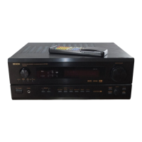
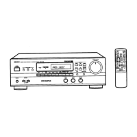
Guide to using the remote control, including battery installation and operation range.

Operating the AVR-900

Playing Audio Sources

How to select and play audio from connected sources in stereo mode.

Simulcast and Headphone Listening

Monitoring video sources while listening to audio and using headphones.

Using Muting and Recording Functions

Temporarily silencing audio output and recording program sources.

Front Panel Display and Surround Function

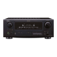
Understanding the front panel display and utilizing various surround sound modes.

Listening to the Radio

Automatic Radio Station Tuning

Automatically scanning and storing FM/AM radio stations for easy access.

Radio Tuning and System Functions

Manual Radio Tuning and Memory

Manually tuning radio stations and managing preset memory.

Troubleshooting Common Issues

Solutions for common operational problems and error indicators.

Technical Specifications

Audio and Tuner Specifications

Detailed technical data for the audio amplifier and tuner sections.

Video, Power, and Remote Specifications

Specifications for video, power supply, dimensions, weight, and remote control.

Disassembly Procedures

Measurement and Memory Clearing

Audio Section Adjustments

Setting Idling Current

Procedure for adjusting the idling current in the audio section using a DC voltmeter.

Parts List Notes and Component Categories

Main Amplifier PCB Parts List

Semiconductors and Resistors for Main Amp

List of semiconductors and resistors for the 1U-2865 Main Amplifier PWB.

Capacitors and Other Parts for Main Amp

List of capacitors and other components for the 1U-2865 Main Amplifier PWB.

Input and Surround PWB Parts List

Rear Amplifier PWB Parts Lists

Exploded View of Components

Parts Lists and Addenda

System Block Diagram

Overall System Signal Flow

Diagram illustrating the overall signal flow and interconnections between major system blocks.

Wiring Diagram

Remote Control Operation and Codes

Schematic Diagrams

Tuner Unit Schematic

Detailed schematic diagram for the Tuner unit, showing circuit components and connections.

Surround Unit Schematic Diagram

Volume Unit Schematic Diagram

Tact Switch, FLD, and Main Unit Schematics

Video Unit Schematic and Connections

Main Unit Schematic Diagrams

Main Unit Circuitry

Detailed schematic diagrams of the Main Unit's internal circuitry.

Rear Amplifier Unit Schematic

Power Supply and AC Outlet Schematics

Related product manuals