Home
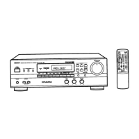
Denon
Stereo Receiver
AVR-900
Denon AVR-900 Service Manual
4
of 1
of 1 rating
50 pages
Give review
Manual
Specs
To Next Page
To Next Page
To Previous Page
To Previous Page
Loading...
241
2399
970
|
Carbon
3.3kohm
1/4W
241
2400
937
|
Carbon
5.6kohm
1/4W
241
2396
928
|
Carbon
1000hm
1/4W
241
2400
937
|
Carbon
5.6kohm
1/4W
241
2396
928
|
Carbon
100chm
1/4W
CAPACITORS
GROUP
253
1181
904
|
Ceramic
0.01p1F/50V
253
4538
949
|
Ceramic
100PF/50V
254
4254
912
|
Electrolytic
22u.F/16V
253
4448
903
|
Ceramic
330PF/50V
OTHERS
PARTS
GROUP
261
0146
006
|
FMCFSK107M2-A
232
9010
009
|
Anti
birdie
filter
LFO02,003
|
232
0085
004
|
:LPF
IC
BU4066BC
IC
TMP87CM71F-6314
IC
SBX1610-52
262
2190
011
499
0150
008
1C702
273
0198
918
271
0102
924
Transistor
2C1815(BL)
Transistor
2SC1015(GR)
TR601,602
TR603,604
TR701,702
|
269
0020
906
|
Transistor
DTC114ES(10k-10k)
Built
in
resistor
Diode
1SS252
Diode
18252
D616
D617
276
0616
907
276
0616
907
Diode
MTZJ8.2B
Diode
1SS252
D701
D701,702
276
0636
903
276
0616
907
LED
SEL1210S
LD701,702
RESISTORS
GROUP
393
9434
906
CAPACITORS
GROUP
254
4262
927
|
Electrolytic
47pF/10V
CE04W1A470M
254
4254776
|
Electrolytic
470F/16V
CEO4W1C471M
253
4535
955
|
Ceramic
5pF/50V
CC45SL1H050C
254
4252
778
|
Electrolytic
1000uF/10V
CE04W1A102MC
1U-2889B
TUNER
&
VOLUME
P.W.B.
UNIT
ASS’Y
for
Asia
model
(Same
as
1U-2889
except
the
followings)
RESISTORS
GROUP
241
2402
935
|
Carbon
39kohm
1/4W
Change
254
4260
977
|
Electrolytic
4.7uF/50V
CEO4W1H4R7M
254
4250
929
|
Electrolytic
100uF/6.3V
CE04W0J101M
|
CAPACITTORSGROUPssSsSs=isd
AP
|
CAPACITTORSGROUPssSsSs=isd
GROUP
253
1181
904
|Ceramic
0.01,F/50V
CK45F1H103Z
253
1180
934
|
Ceramic
1200PF/50V
Change
CN25A
205
0736
089
|25P
FFC
connector
base
205
0075025
|2P
terminal
203
5080
019
|3P
SCN-SCN
connector
cord
205
0970
049
|4P
TAC-L
socket
204
2751
001
|9P
PH-SAN
connector
cord
393
4155
002
|FLD
(FIP14AM7R)
JK601,602
|
204
8468
000
in
j
$W701~704)
212
4789
001
i
SW708~713]
212
4789
001
i
SW719~730|
212
4789
001
i
Crystal
(CO.DCRHTP4.00M)
29
28
30
Table of Contents
Table of Contents
1
Wire Arrangement
10
Disassembly
11
Connection Diagram of Measuring Instruments
12
Semiconductors
14
Note for Parts List
23
Parts List of P. W. Board
24
Printed Wiring Board
31
Exploded View
36
Parts List of Exploded View
37
Addendum Parts List
37
Block Diagram
38
Wiring Diagram
39
Remote Control Unit (Rc-195)
40
Schematic Diagram
41
4
Based on 1 rating
Ask a question
Give review
Questions and Answers:
Need help?
Do you have a question about the Denon AVR-900 and is the answer not in the manual?
Ask a question
Denon AVR-900 Specifications
General
Input sensitivity
2.5mV (MM), 150mV (line)
Output
150mV (line)
Tuning range
FM
Signal to noise ratio
86dB (MM)
Speaker load impedance
16Ω
Related product manuals
Denon AVR-989
86 pages
Denon AVR-983
76 pages
Denon AVR-991
116 pages
Denon AVR-990
108 pages
Denon AVR-982
128 pages
Denon AVR-2801/981
127 pages
Denon AVR-85
38 pages
Denon AVR-887
82 pages
Denon AVR-786
68 pages
Denon AVR-888
78 pages
Denon AVR-391
111 pages
Denon AVR-591
83 pages