29
AVR-2809CI / AVR-2809 / AVR-989 /AVC-2809
TROUBLE SHOOTING
1. POWER
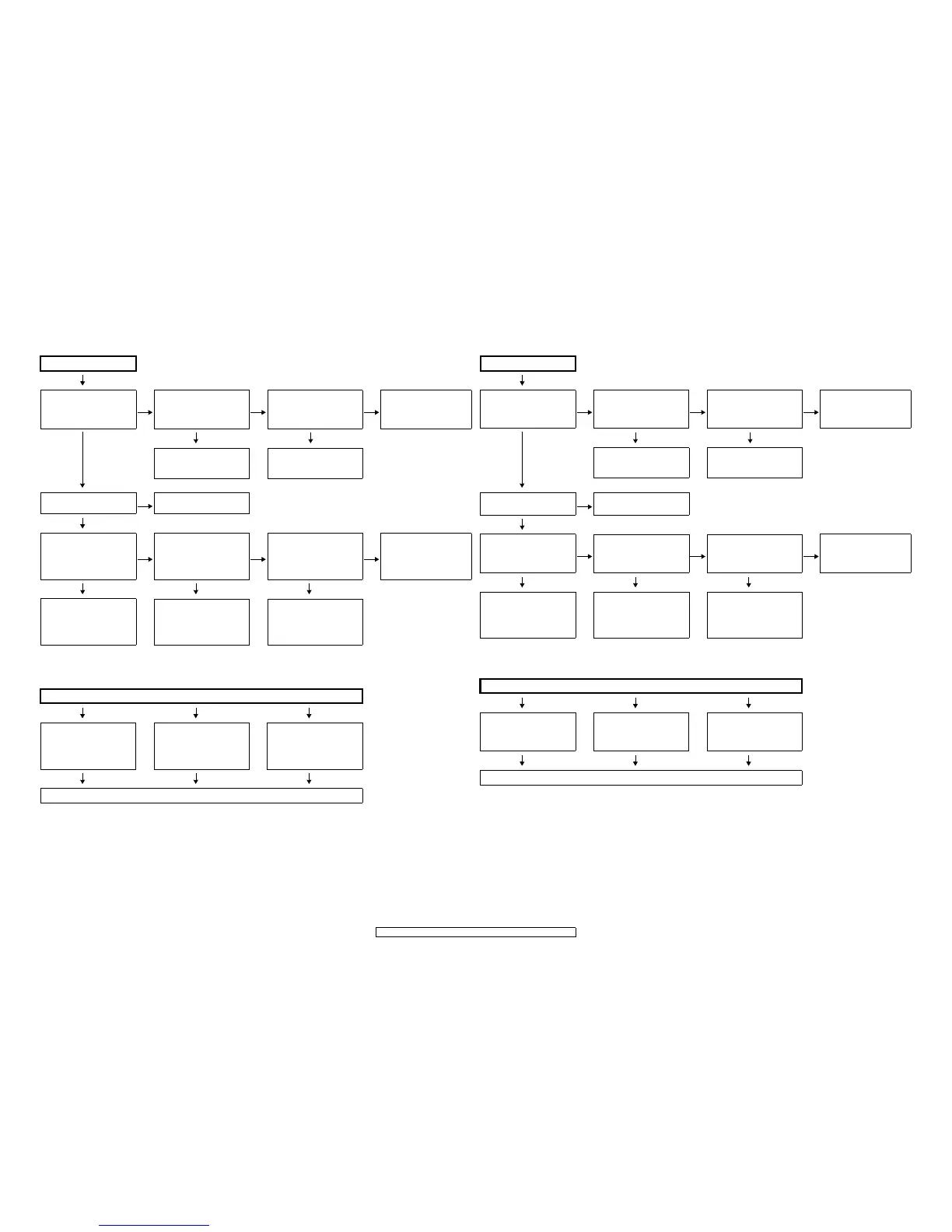
1.1. Power not turn on
1.2. Fuse is blown
Power not turn on
YES
Is the ON/STANDBY indicator
on the front panel flashing red?
YES
Are there any incomplete con-
nections in the connectors con-
necting between the various
circuit boards?
NO
Is there a short circuit between
the speaker terminals and the
ground?
YES
Correct the short circuit
between the speaker and the
ground.
YES NO
NO
Connect the connectors prop-
erly.
Check for damage in the power
amplifier circuitry parts and
replace any defective parts.
Is the fuse blown?
NO
Refer to Fuse is blown
YES
Does the power turn on when
the POWER switch is turned off
then back on?
NO
Is a DC 6V voltage being sup-
plied from the 8U-110031-3
board (CX126 pins 7 and 8) to
the ucom?
NO
Is a DC 6V voltage output when
the connector supplying the
power from the 8U-110031-3
board to the ucom (CX126) is
unplugged?
NO
Check the parts from the 8U-
210019-4 board’s IC904
periphery circuitry to the pri-
mary circuitry and replace
any defective parts.
YES YES YES
Check the primary circuitry
parts including the POWER
switch (for poor contacts, etc.),
and replace any defective
parts.
Check the 8U-110031-1
board's ucom periphery cir-
cuitry and replace any defec-
tive parts.
Check the circuitry and parts
from CX126 on the 8U-110031-
3 board to the ucom for dam-
age and short-circuits, and
replace any defective parts.
Fuse is blown
YES YES YES
Check for leaks or short circuits
in the primary side parts, and
replace any defective parts.
Check for short circuits in the
rectifier diodes and circuitry of
the secondary side rectifying
circuits, and replace any defec-
tive parts.
Check for short circuits in the
power stabilizer unit's regula-
tor output terminal and the
ground, and replace any defec-
tive parts.
YES YES YES
After repairing, also replace the fuse.
トラブルシューティング
1. 電源
1.1. 電源が入らない
1.2. ヒューズが断線している
電源が入らない
YES
フロントパネルの
ON/STANDBY インジ
ケータが赤色点滅しています
か?
YES
各基板間を接続しているコネ
クターに不完全な接続部分は
ありますか?
NO
SP 端子と GND 間が短絡してい
ますか?
YES
SP 端子と GND 間の短絡を取
り除いてください。
YES NO
NO
コネクターを正しく接続して
ください。
POWERAMP 回路の部品の破損
を確認し、不良部品を交換して
ください。
ヒューズは断線していません
か?
NO
ヒューズが断線しているを参
照してください。
YES
POWERSW を OFF にして、再
度 POWERSW を ON にすると
電源が入りますか?
NO
8U-110031-3 基板(CX126 の 7、
8番ピン)からマイコンに DC6V
が供給されていますか?
NO
8U-110031-3基板からマイコン
ヘ電源を供給しているコネク
タ(CX126)を抜いて DC6V が
出力されていますか?
NO
8U-210019-4 基板の IC904 の
周辺回路〜 1 次回路までの部
品を確認し、不良部品を交換
してください。
YES YES YES
POWERSW等を含む 1次回路部
品 ( 接触不良等 ) を確認し、不
良部品を交換してください。
8U-110031-1のマイコン周辺回
路を確認し、不良部品を交換し
てください。
8U-110031-3 基板の CX126 以
降からマイコン電源までの回
路および部品の破損や短絡を
確認し、不良部品を交換して
ください
ヒューズが断線している
YES YES YES
1 次側の部品にリークまたは短
絡を確認し、不良部品を交換し
てください。
2 次側のそれぞれの整流回路
で、整流ダイオードおよび回路の
短絡を確認し、不良部品を交換
してください。
電源安定化部のレギュレータ
の出力端子と GND の短絡を確
認し、短絡している場合は、不
良部品を交換してくだい。
YES YES YES
修理後、FUSE も交換してください。
 Loading...