7
P/N: PM1548
REV. 1.2, JUL. 02, 2010
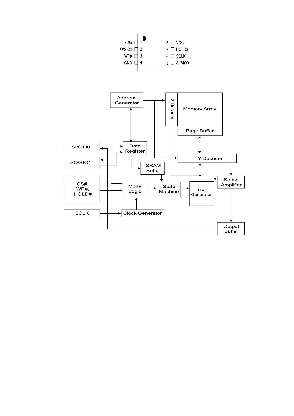
PIN CONFIGURATIONS
SYMBOL DESCRIPTION
CS# Chip Select
SI/SIO0
Serial Data Input (for 1 x I/O)/ Serial Data
Input & Output (for Dual Output mode)
SO/SIO1
Serial Data Output (for 1 x I/O)/ Serial Data
Output (for Dual Output mode)
Clock Input
WP# Write protection
HOLD#
Hold, to pause the device without
deselecting the device
VCC
GND Ground
PIN DESCRIPTION
16-PIN SOP (300mil) for MX25L1606E only
8-LAND WSON (6x5mm), USON (4x4mm)
8-PIN SOP (200mil, 150mil)
8-PIN PDIP (300mil)
 Loading...


