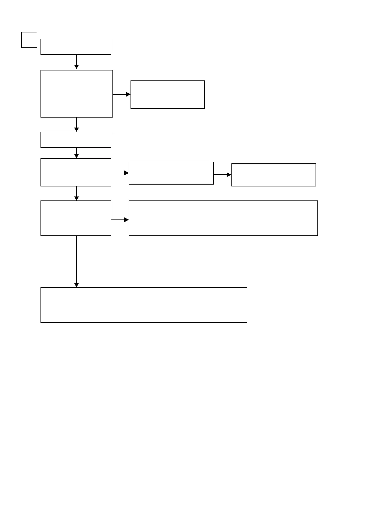
Input
COMPONENT
C
Check the set value of each
IC. Are the voltage values as
follows?
DIGITAL PCB
BN21A - 2pin : Lo(0V)
BN21A - 1pin : Hi(3.3V)
Is the power supply voltage
being output correctly?
V+5V : C5107 : + side
V-5V : C5109 : - side
Is a signal being output from
the video amplier?
COMP-Y : J5002
COMP-CB : J5001
COMP-CR : BN21B 11pin
•Check the connection between the FRONT CONNECTOR PCB and the VIDEO PCB
•Check the soldering of the BN21B(VIDEO PCB) / BN21A(DIGITAL PCB )
/ CN21A(FRONT CONNECTOR PCB) / CN21B(FRONT CONNECTOR PCB)
•Check the soldering of the JK515(E3)
Use the jigs to extend the
DIGITAL PCB.
The DIGITAL PCB is faulty.
Check the connection between the
SIDE CONNECTOR PCB and the
VIDEO PCB.
NO
NO
NO
YES
YES
YES
b
All parts are VIDEO PCB parts unless otherwise specied.
w
q
e
r
•Check the IC516 power supply voltage and check the soldering of the surrounding
circuits.
•The circuit between IC516 and JK515/BN21B are faulty.
The regulator part of REG_SPK
PCB is faulty.
NO
92
 Loading...


