TROUBLE SHOOTING
1. POWER
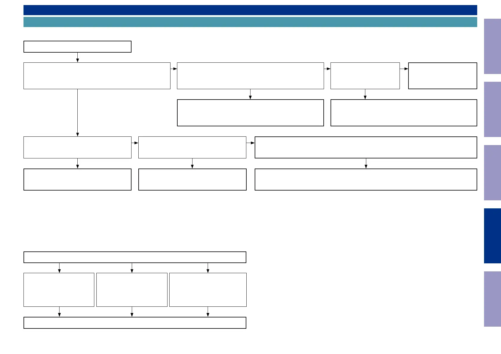
1.1. The unit does not power on
Measure the voltage of the DIGITAL PCB [CN903 : 5, 6pin].
Is DC5.2V supplied?
Disconnect the connector [CN903] that supplies power from the
SMPS PCB to the DIGITAL PCB and measure the voltage of the SMPS
PCB [BN901 : 5, 6pin].
Is DC5.2V supplied?
• Check the contact between [CN903 and BN901].
• Check for breakages and short circuits in the circuits and parts
between CN903 on the DIGITAL PCB and the microprocessor power
supply and replace any faulty parts.
Is the fuse blown out?
See "1.2. Fuse is blown"
TO "6. SMPS"
The unit does not power on
Disconnect the MAIN PCB connector [CN971] and
check "3-2. Protection History Display Mode".
Does the FLD light go out after several seconds,
and does the power indicator LED then blink in
green or white?
Is the fuse blown out?
See "1.2. Fuse is blown"
• Check if there is a normal connection between the DIGITAL PCB [CN69B] and the FRONT PCB [CN69A].
• Check if there is a normal connection between the MAIN TRANS and the FRONT PCB [CN605].
Check the microcomputer peripheral circuits and power supply circuits of the DIGITAL PCB and replace
any faulty parts.
Check for leaks and short circuits
in the parts on the primary side.
Replace any faulty parts.
Blown fuse
Check the rectier diode in the
rectier circuit on the secondary
side, and check for short circuits.
Replace any faulty parts.
Replace the fuse after repair.
Check for short circuits between the
regulator output terminal and GND
in the power supply stabilization
circuit. Replace faulty parts if there
is a short circuit.
1.2. Fuse is blown
YES
YESYES
YES YES
YES
NO
NO NO
NONO
Before Servicing
This Unit
Electrical Mechanical Repair Information Updating
89

 Loading...