62
AK4104ET (MAIN : IC406)
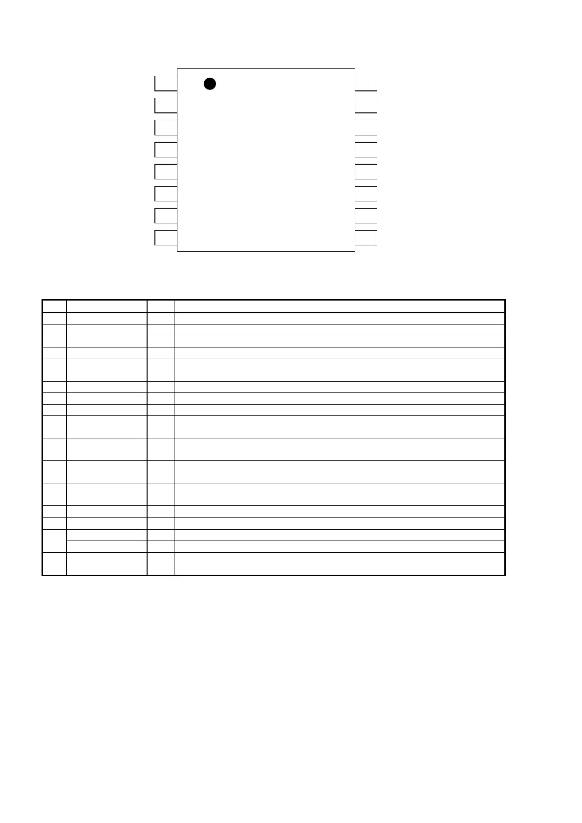
AK4104ET Pin Function
[AK4104]
■ Ordering Guide
AK4104ET −20 ∼ +85°C 16pin TSSOP (0.65mm pitch)
AKD4104 Evaluation Board for AK4104
■ Pin Layout
1
MCLK
LRCK
BICK
CSN
CCLK
CDTI
AK4104
Top
View
2
3
4
5
6
7
8
TX
VDD
CDTO/ SDTI2
VSS
TEST4
TEST3
TEST2
16
15
14
13
12
11
10
9
PDN
SDTI1
TEST1
MS0642-E-00 2007/07
- 3 -
No. Pin Name I/O Function
1 MCLK I Master Clock Input Pin
2 BICK I Audio Serial Data Clock Pin
3 SDTI1 I Audio Serial Data Input 1 Pin
4 LRCK I Input Channel Clock Pin
5 PDN I
Power Down and Reset Pin
“L”: Power down and Reset, “H”: Power up
6 CSN I Chip Select Pin
7 CCLK I Control Data Clock Pin
8 CDTI I Control Data Input Pin
9 TEST1 I
TEST Pin
This pin should be connected to VDD.
10 TEST2 O
TEST Pin
This pin should be OPEN.
11 TEST3 O
TEST Pin
This pin should be OPEN.
12 TEST4 O
TEST Pin
This pin should be OPEN.
13 VSS - Ground Pin
14 VDD -
Power Supply Pin, 2.7 ∼ 3.6V
CDTO O Control Data Output Pin, The output is “Hi-Z” when PDN pin = “L”.
15
SDTI2 I Audio Serial Data Input 2 Pin
Transmit Channel Output Pin, The output is “L” when PDN pin = “L” or RSTN bit
=“0” or PW bit = “0” or MCLK stops.
16 TX O
Note: All digital input pins should not be left floating.
MS0642-E-00 2007/07
- 4 -
 Loading...