EasyManua.ls Logo

Denon DR-M33HX - CTS Adjustment

Denon DR-M33HX
48 pages
Print Icon
To Next Page IconTo Next Page
To Previous Page IconTo Previous Page
Loading...
(2)
Adjusting
the
record/playback
levels
1)
Load
the
test
tape
DX7/50N
and
record
a
signal
of
IkHz
(-41
dB).
2)
Adjust
RT103
(L
ch),
RT203
(R
ch)
so
that
the
output
level
is
the
same
when
the
MONITOR
switch
is
switched
from
SOURCE
to
TAPE
position.
3)
Load
the
test
tape
and
record
a
signal
of
1kHz
(—41
dB).
4)
Adjust
RT
102
(L
ch),
RT
202
(R
ch)
so
that
the
output
level
is
the
same
when
the
MONITOR
switch
is
switched
from
SOURCE
to
TAPE
position.
5)
Load
the
test
tape
DX3
and
record
a
signal
of
1kHz
(-41
dB).
6)
Adjust
RT104
(L
ch),
RT
204
(R
ch)
so
that
the
output
level
is
the
same
when
the
MONITOR
switch
is
switched
from
SOURCE
to
TAPE
position.
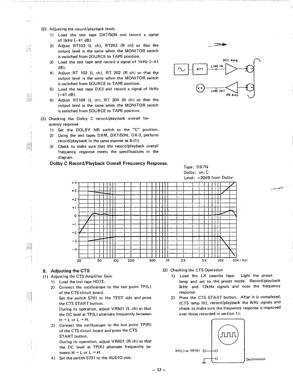
(3)
Checking
the
Dolby
C
record/playback
overall
fre¬
quency
response
1)
Set
the
DOLBY
NR
switch
to
the
"C"
position.
2)
Using
the
test
tapes
DXM,
DX7/50N,
DX-3,
perform
record/playback
in
the
same
manner
as
8-(1).
3)
Check
to
make
sure
that
the
record/playback
overall
frequency
response
meets
the
specifications
in
the
diagram.
Dolby
C
Record/Playback
Overall
Frequency
Response.
Tape;
DX7N
Dolby:
on,
C
Level;
—20dB
from
Dolby
■
ggaMB
—
BasaaBBBBsan
iBsaga
■
IBBBIlIBBBiBaaHBHiaiQaHl
■
■
■■■
iiaiaHaBBMiiBiBI
■
BiHfliia
B
aaaaBBBBBBBM
0--
^
“
y
*
/
HaiaBHiiiBB
■
■
■■■
lIBBaBBaBHIIIMBI
“3--
1
1
1
ini
1
1
1
M
MiMxr
]
■
■
■■■
iiHaBBaMBiiiwn
-
V
\
20
50
100
200
500
IK
2K
5K
lOK
20K
9.
Adjusting
the
CTS
(1)
Adjusting
the
CTS
Amplifier
Gain
1)
Load
the
test
tape
HD7E.
2)
Connect
the
oscilloscope
to
the
test
point
TP(L)
of
the
CTS
circuit
board.
Set
the
switch
S701
to
the
TEST
side
and
press
the
CTS
START
button.
During
its
operation,
adjust
VR501
(L
ch)
so
that
the
DC
level
at
TP(L)
alternate
frequently
between
H
L
or
L
->
■
H.
3)
Connect
the
oscilloscope
to
the
test
point
TP(R)
of
the
CTS
circuit
board
and
press
the
CTS
START
button.
During
its
operation,
adjust
VR601
(R
ch)
so
that
the
DC
level
at
TP(R)
alternate
frequently
be¬
tween
H
->
■
L
or
L
->
■
H.
4)
Set
the
switch
S701
to
the
AUDIO
side.
(2)
Checking
the
CTS
Operation
1)
Load
the
LX
cassette
tape.
Light
the
preset
lamp
and
set
to
the
preset
mode.
Record/playback
IkHz
and
12kHz
signals
and
note
the
frequency
response.
2)
Press
the
CTS
START
button.
After
it
is
completed,
(CTS
lamp
lit),
record/playback
the
IkHz
signals
and
check
to
make
sure
the
frequency
response
is
improved
over
those
recorded
in
section
1).
-
1
7
-

Table of Contents