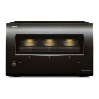
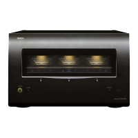
oAbout channel level meter
You can select
the
output
level (dB indicator)
of
each
power
amp
channel
to
check
the
meter.
If a sine
wave
is input.
the
output
power
for
the
meter
indicator is
as
shown
in
the
following
table.
•
When
NORMAL
connection
or
Bi-AMP connection is used
Output
4 O/ohms load 6
O/ohms
load 8
O/ohms
load
indicator
o(dB)
300
IV'J)
200
(VII)
150(W)
-10
(dB)
30
IV'J)
20(W)
15
IV'J)
-20
(dB)
3
IV'J)
2(W)
1.5(W)
-30
(dB)
300 (mW) 200 (mW) 150 (mW)
-40
(dB)
30
(mW)
20
(mW) 15 (mW)
-50
(dB) 3 (mW) 2 (mW) 1.5 (mW)
•
When
BRIDGE connection is used
Output
4
O/ohms
load 6
O/ohms
load 8
O/ohms
load
indicator
o(dB)
1200
(VII)
*
800(W)
* 600
(W)*
-10
(dB)
120(W)
80(W)
60
IV'J)
-20
(dB)
12(W)
8
IV'J)
6(W)
-30
(dB) 1200 (mW) 800 (mW)
600 (mW)
-40
(dB) 120 (mW)
80
(mW)
60
(mW)
-50
(dB) 12 (mW) 8 (mW) 6 (mW)
*Possible
output
by POA-A1HDCI is up
to
the
rated
output.
-NI"-
When
outputting
a program source
that
has data such as SACD.
which
is higher than the audible band.
the
indicator
moves
differently
than
the
volume
you hear.
I
-~-
•
PRE
AMP
CONTROL
UNK
indicator··....
...
. (6)
oCenter channel
meter
select button (METER)
(13)
i>
Center channel level
meter
.(13)
..
Right channel
meter
select buttons (METER)
(13)
• Right channel
meter
indicators
(R1
/ R2 / R3 / R4)
(13)
..
Right channel level meter.......... .
(13)
• METER ON/OFF button
(13)
1..~
~ :Ll··~··i
-If
·:11:";
---L.I~
J
L:
~
;.
..
~
..
~J
========
=!=
•
Co.
:.
0
:.
~~
liI
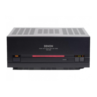
Part
Names
and Functions
• Power operation button (ON/STANDBY)··
(13)
f)
Power indicator·· .
(13)
• Power switch
(_ON
.OFF)·····
.
(13)
o Left channel meter select button (METER)
(13)
oLeft channel meter indicators
(L
1 / L2 / L3 / L4)··
(13)
oLeft channel level
meter
.
..
(13)
• Center channel
meter
indicators
(L5
/ AS)·············
.. ·· ..
··.·····
(13)
-~;
3
 Loading...