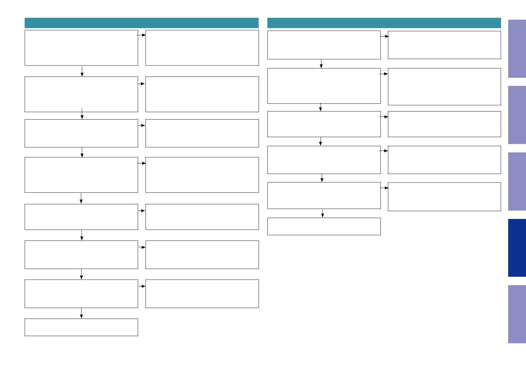
6. TUNER cannot be played. 7. Analog input cannot be played.
Is there any abnormality below?
Tuner&Optical PCB
TM11 : 3pin(TU+5V)
Is [TM11] "Hi"?
Tuner&Optical PCB
TM11 : 7pin(TU_RST)
NO
Is there any abnormality below?
Tuner&Optical PCB Tuner module
[Analog audio signal]
TM11 : 1pin(L_OUT)
2pin(R_OUT)
YES
Is there any abnormality below?
MAIN PCB
[IC30] : 1pin(V+(+7.5VA))
32pin(V-(-7.5VA))
NO
Is there any abnormality below?
MAIN PCB [Analog audio signal]
[IC30] : 3pin(INA1)
4pin(INB1)
NO
Is there any abnormality below?
MAIN PCB [Analog audio signal]
[IC30] : 29pin(OUTB1)
30pin(OUTA1)
NO
Is there any abnormality below?
MAIN PCB [DIR1 Analog audio signal]
IC37 : 47pin(VINL)
48pin(VINR)
NO
"4. No sound is output from the speakers or head-
phones, or noise occurs"
NO
Tuner&Optical PCB [WF15] or the SMPS power
supply circuit may be malfunctioning.
Repair the part where the abnormality is occur-
ring or check each part according to the area from
"YES" in the ow chart for "1.3. Power Supply Volt-
age Abnormalities".
YES
The TUNER modulator [TM11], MCU [IC20] or the
circuit around the MCU may be malfunctioning.
Check for abnormalities and repair them.
NO
Tuner&Optical PCB or the Tuner module may be
malfunctioning.
Replace the malfunctioning part.
YES
[IC31]+7.5VA,[IC32]-7.5VA or SMPS power supply
circuit may be malfunctioning.
Repair the part where the abnormality is occur-
ring or check each part according to the area from
"YES" in the ow chart for "1.3. Power Supply Volt-
age Abnormalities".
YES
Check for abnormalities in the signal path be-
tween Tuner&Optical PCB and MAIN PCB [IC30],
and repair them.
YES
The circuit around MAIN PCB [IC30] is faulty.
Repair the abnormal area.
YES
The circuit around MAIN PCB [IC35], [IC35] is
faulty.
Repair the abnormal area.
YES
Is there any abnormality below?
MAIN PCB [Analog audio signal]
JK22 : 1pin(R_CH)
3pin(L_CH)
NO
Is there any abnormality below?
MAIN PCB
IC30 : 1pin(V+(+7.5VA))
32pin(V-(-7.5VA))
Is there any abnormality below?
MAIN PCB [Analog audio signal]
IC30 : 6pin(INA2)
7pin(INB2)
NO
NO
Is there any abnormality below?
MAIN PCB [Analog audio signal]
IC30 : 29pin(OUTB1)
30pin(OUTA1)
Is there any abnormality below?
MAIN PCB [DIR1 Analog audio signal]
IC37 : 47pin(VINL)
47pin(VINR)
NO
NO
"4. No sound is output from the speakers or head-
phones, or noise occurs"
Replace the MAIN PCB [JK22].
YES
[IC31]+7.5VA, [IC32]-7.5VA or SMPS power sup-
ply circuit may be malfunctioning.
Repair the part where the abnormality is occur-
ring or check each part according to the area
from "YES" in the ow chart for "1.3. Power Sup-
ply Voltage Abnormalities".
YES
Check for abnormalities in the signal path
between MAIN PCB [JK22] and MAIN PCB [IC30]
and repair them.
YES
The circuit around MAIN PCB [IC30], [IC30] is
faulty.
Repair the abnormal area.
YES
The circuit around MAIN PCB [IC30], [IC30] is
faulty.
Repair the abnormal area.
YES
Before Servicing
This Unit
Electrical Mechanical Repair Information Updating
52
 Loading...


