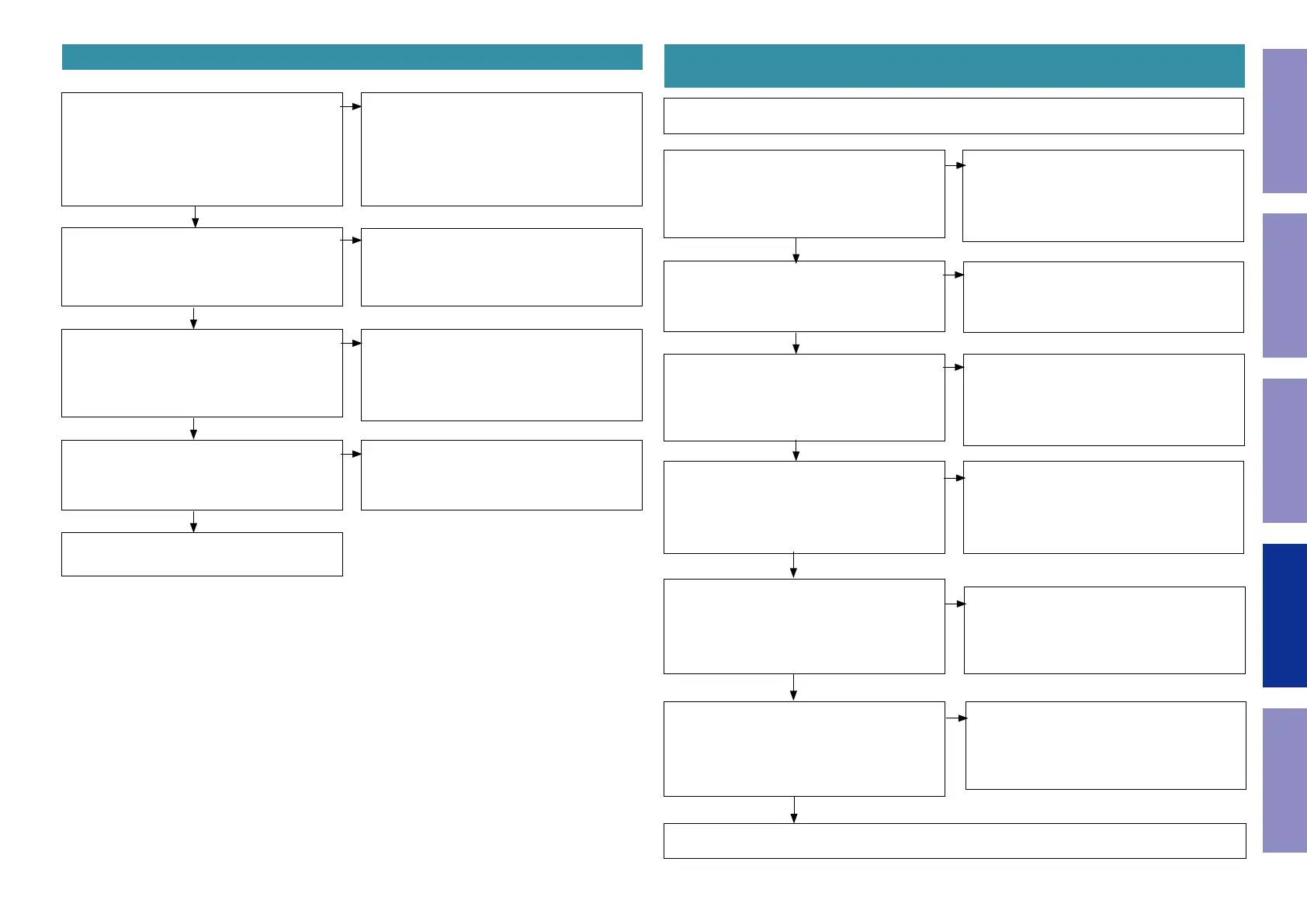
8. No Audio Output during OPT or COAX Playback
9. No Audio Output during USB File Playback (USB-A input), File
Playback on a Server or Internet Radio and Bluetooth Playback
Before testing circuit operation, check if the le to be played back is in a supported format and network
settings are correct.
Is there any abnormality below?
NETWORK PCB
IC113 : 2pin(AIOS4_MCLK_I2S_0)
IC114 : 2pin(AIOS4_LRCK_I2S_0)
4pin(AIOS4_SCLK_I2S_0)
6pin(AIOS4_I2S_0_OUT)
NO
Check for abnormalities in the circuits surround-
ing [IC113, IC114], and repair them.
YES
NO
Is there any abnormality below?
NETWORK PCB
IC113 : 4pin(AIOS4_MCLK_I2S_0)
IC114 : 8pin(AIOS4_LRCK_I2S_0)
16pin(AIOS4_SCLK_I2S_0)
14pin(AIOS4_I2S_0_OUT)
The [IC113, IC114] may be malfunctioning.
Replace the malfunctioning part.
Is there any abnormality below?
MAIN PCB [DIR1 digital audio signal (I2S)]
IC37 : 7pin(AIOS4_MCLKO)
8pin(AIOS4_SCLK_I2S_0)
9pin(AIOS4_LRCK_I2S_0)
10pin(AIOS4_SDOUT_I2S_0)]
Check for abnormalities in the signal path be-
tween NETWORK PCB[IC113, IC114] and [IC37]
DIR1, and repair them.
NO
YES
Is there any abnormality below?
NETWORK PCB
CN111 : 4-6pin(LEGO5V)
Can les be played?
Is there any abnormality below?
NETWORK PCB
IC113 : 5pin(VCC(NET3.3V))
IC114 : 20pin(NET3.3V)
[Q1101 : (LEGO5V)], or the SMPS power supply
circuit may be malfunctioning.
Repair the part where the abnormality is occur-
ring or check each part according to the area
from "YES" in the ow chart for "1.3. Power Sup-
ply Voltage Abnormalities".
[Q1102 : (NET3.3V)], or the SMPS power supply
circuit may be malfunctioning.
Repair the part where the abnormality is occur-
ring or check each part according to the area
from "YES" in the ow chart for "1.3. Power Sup-
ply Voltage Abnormalities".
Check the connectors of each part or perform a
factory reset. If the device cannot be restored,
replace the LEGO module.
YES
NO
YES
NO
YES
"4. No sound is output from the speakers or headphones, or noise occurs"。
NO
YES
Is there any abnormality below?
Tuner&Optical PCB
JK12 : 3pin(VCC(+3.3V))
JK13 : 3pin(VCC(+3.3V))
Is there any abnormality below?
[DIR1 Digital audio signal (SPDIF)]
Tuner&Optical PCB
JK12 : 1pin
JK13 : 1pin
Is there any abnormality below?
MAIN PCB
IC33 : 5pin (+3.3VD)
IC34 : 5pin (+3.3VD)
NO
Is there any abnormality below?
MAIN PCB [DIR1 digital audio signal (SPDIF)]IC37
: 32pin,33pin(OPT1,OPT2)
NO
NO
"4. No sound is output from the speakers or head-
phones, or noise occurs"
NO
[BN16 : 1pin(+3.3V_OPT)], the circuit surround-
ing [Q210] or the SMPS power supply circuit may
be malfunctioning.
Repair the part where the abnormality is occur-
ring or check each part according to the area
from "YES" in the ow chart for "1.3. Power Sup-
ply Voltage Abnormalities".
YES
Replace the Tuner&Optical PCB [JK12, JK13].
YES
MAIN PCB [IC24] or the SMPS power supply
circuit may be malfunctioning.
Repair the part where the abnormality is occur-
ring or check each part according to the area
from "YES" in the ow chart for "1.3. Power Sup-
ply Voltage Abnormalities".
YES
Check for abnormalities in the signal path be-
tween [IC33, IC34] and DIR1[IC37], and repair
them.
YES
Before Servicing
This Unit
Electrical Mechanical Repair Information Updating
53
 Loading...


