


B
Bryan RiceAug 25, 2025
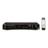
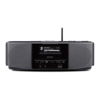
How to fix a Denon S-52 Media Converter remote that is not working?
- SStephen DavisAug 25, 2025
If your Denon Media Converter isn't responding to the remote control, try these steps: 1. Replace the batteries with new ones. 2. Ensure you are within the specified operating range. 3. Remove any obstacles between the remote and the main unit. 4. Verify the batteries are inserted correctly, matching the polarity marks. 5. Move the unit away from strong light sources like direct sunlight or fluorescent lights.