Operation Section
1
–
22
8. OPERATION OF CONTROL SYSTEM COMPONENTS
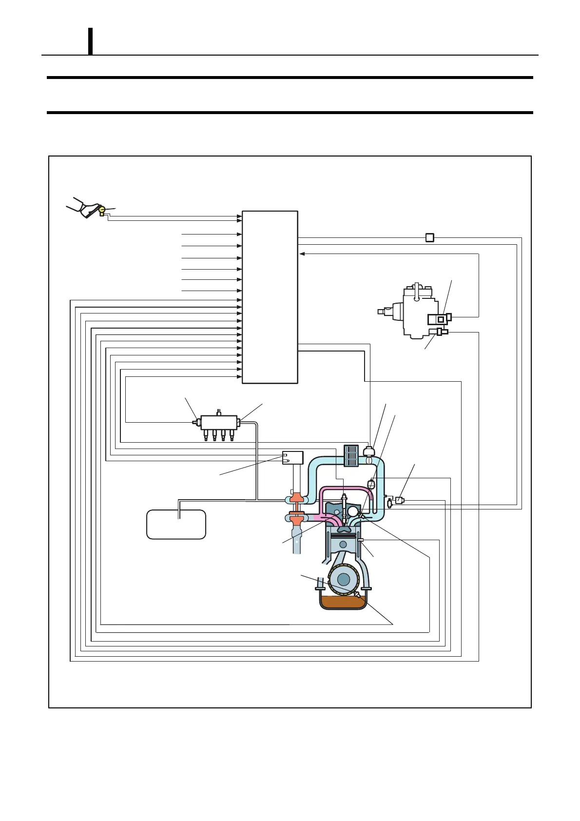
8.1 Engine Control System Diagram
8.2 Engine ECU (Electronic Control Unit)
z This is the command center that controls the fuel injection system and the engine operation in general.
Q001247E
Rail
Rail Pressure Sensor
(Pc Sensor)
Pressure limiter
injector
Engine ECU
SCV
(Sucton Control Valve)
Glow Relay
Crankshaft Position Sensor
(NE Sensor)
Cylinder Recognition
Position Sensor
(TDC Sensor)
Turbo Pressure
Sensor
Electronic Control
Throttle
Fuel Tank
Accelerator Position Sensor
Ignition Switch Signal
Starter Signal
Vihicle Speed Signal
Mitsubishi Diagnosis Tool (MUDIII)
Battery Voltage
Other Signals
Air Mass Flow Sensor
(With Intake Air Temperature)
Fuel Temperature
Sensor
Coolant
Temperature
Sensor