Operation Section
1
–
42
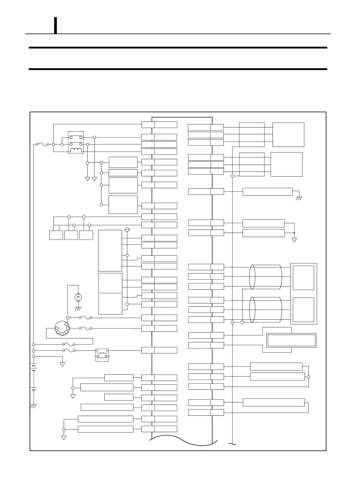
15. EXTERNAL WIRING DIAGRAM
15.1 Engine ECU External Wiring Diagram
z The wiring diagram below is common to the 4D56/4M41 model.
Q001257E
Throttle
Solenoid Valve
SCV
(Suction
Control Valve)
Air
Conditioning
Relay
FAN Relay
Control (ECCS) Relay
P1 P2
BATT
Air Conditioning 2 Switch
Air Conditioning 1 Switch
Glow Light
Glow Pulg Relay
BATT
Key
ACC
I
S
OFF
Battery
Starter
Motor
EGR
Position
Sensor
EGR
DC Motor
Elecronic
Throttle
Control
Body
Earth
P1
Engine Warning Light
Tacho Meter
Vehicle Speed Sensor
NE+
NE-
A46
A65
A-VCC3
A-VCC4
Crankshaft
Position
Sensor
Cylinder
Recognition
Sensor
A44
A45
BATT
B40
A/C2 SW
A31
A/C1 SW
A12
WA16
GROW L
A38
GROW R
A37
IG-SW
B26
STA-SW
B18
EGR LIFT RTN
A72
EGR LIFT
A53
B05
EGR -
A07
EGR +A08
ETC -
B37
ETC +
B35
ETCP-S
ETCP-M
A81
SPDB16
TACHO
B25
+BP
B38
+BP
B39
M-REL
B24
THR
A15
C FAN R
A27
A/C R
A26
CAN1-H
CAN1-L
B14
B06
SCV
A17
G+
G-
A47
A66
PS-SW
Power Steering Switch
Reverse Shift Switch
1st Shift Switch
Air Temperature Sensor
Fuel Temperature Sensor
Body
Earth
BATT
Accelerator
Position Sensor
B30
MT REV SW
B20
MT 1ST SW
B19
A-VCC1
B01
APS1
B02
APS1 GND
B03
A-VCC2
B09
APS2
B10
APS2 GND
B11
A10
SCV-
SCV
(Suction Control Valve)
SCV+
A29
A79
THF
THA
A50
THFRTN
A69
Coolant Temperature Sensor
A51
THWRTN
THW
A70