Operation Section
1
–
43
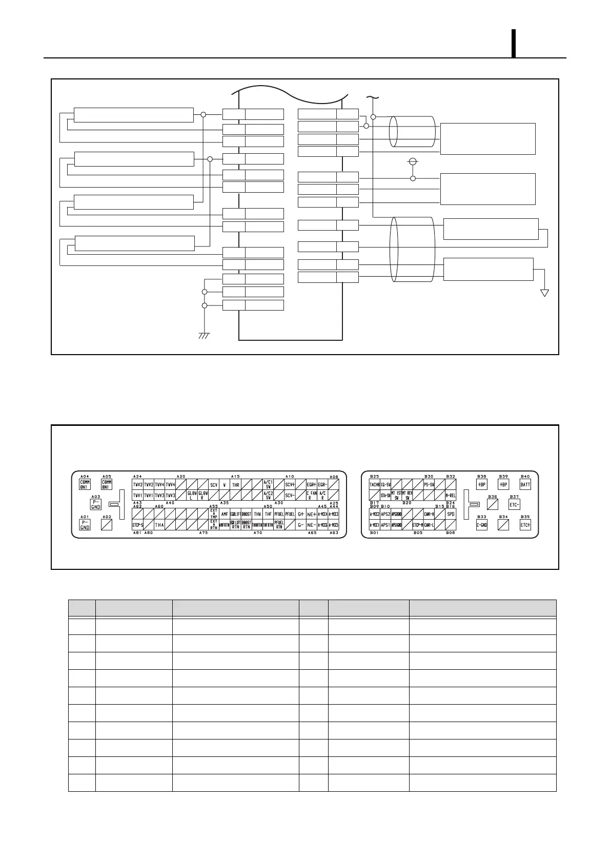
15.2 Engine ECU Connector Diagram
z The connector diagram and terminal below are common to the 4D56/4M41 model.
Terminal Connections (1)
No. Pin Symbol Signal Name No. Pin Symbol Signal Name
A01 P-GND Power Ground A11 — —
A02 — — A12 A/C1 SW Air Conditioning 1 Switch
A03 P-GND Power Ground A13 — —
A04 COMMON 1 INJ#1/#4 BATT. A14 — —
A05 COMMON 1 INJ#2/#3 BATT. A15 THR Throttle Solenoid Valve
A06 — — A16 W EngineWarning Light
A07 EGR- EGR-DC Motor (-) A17 SCV SCV (Suction Control Valve)
A08 EGR+ EGR-DC Motor (+) A18 — —
A09 — — A19 — —
A10 SCV+ SCV (Suction Control Valve) A20 — —
Q001258E
Rail Pressure Sensor
(Pc Sensor)
EXT
Air Temperature Sensor
Airflow Sensor
P1
Turbo Pressure Sensor
COMMON1
A04
TWV1
A43
TWV1
A42
COMMON1
A05
TWV2
TWV2
A24
Injector3 Drive (#4 Cylinder)
A23
TWV3
A41
TWV3
A40
TWV4
A22
TWV4
A21
P-GND
Body Earth
P-GND
C-GND
A01
A03
B33
A48
PFUEL1
A49
A63
PFUEL2
A-VCC5
A68
PFUEL RTN
A64
A52
BOOST
A71
BOOST RTN
A-VCC6
A55
A74
A54
AMF
A73
AMF RTN
EXT-A-TMP
EXT-A-RTN
Injector4 Drive (#2 Cylinder)
Injector2 Drive (#3 Cylinder)
Injector1 Drive (#1 Cylinder)
Q001259E