Operation Section
1
–
23
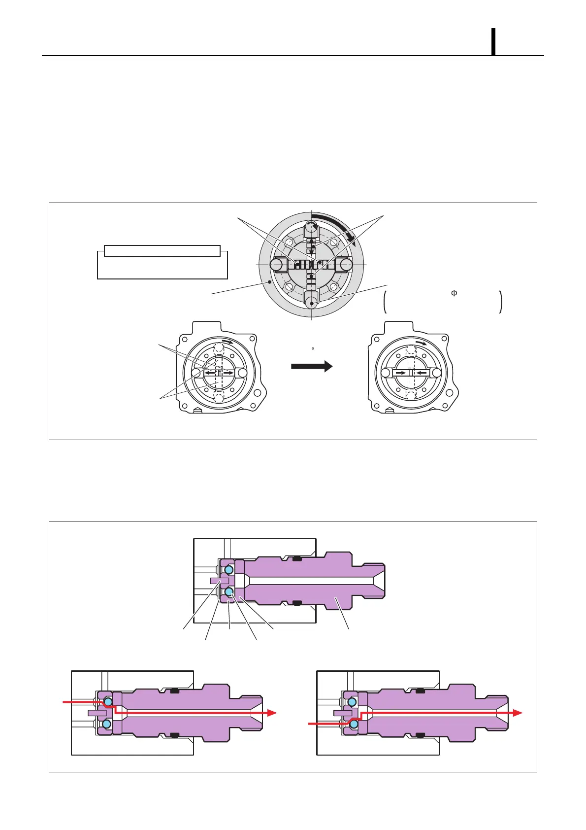
Pumping Mechanism (Plunger, Inner Cam, Roller)
• The pumping mechanism is made up of the plunger, inner cam, and roller, and it draws in the fuel discharged by the
feed pump and pumps it to the rail. Because the drive shaft and the inner cam have an integral construction, the ro-
tation of the drive shaft directly becomes the rotation of the inner cam.
• Two plunger systems are arranged in series (tandem type) inside the inner cam. Plunger 1 is situated horizontally,
and plunger 2 is situated vertically. Plunger 1 and plunger 2 have their suction and compression strokes reversed
(when one is on the intake, the other is discharging), and each plunger discharges twice for each one rotation, so for
one rotation of the supply pump, they discharge a total of four times to the rail.
Delivery Valve
• The delivery valve, which contains two valve balls, delivers the pressurized fuel from plungers 1 and 2 to the rail in
alternating strokes. When the pressure in the plunger exceeds the pressure in the rail, the valve opens to discharge
fuel.
Inner Cam
(Cam Lift: 3.4mm)
Roller
Roller Diameter: 9
Roller Length: 21mm
Material: Reinforced Ceramic
Plunger 1
(Horizontal)
Plunger 2
(Vertical)
· Plunger 1: Medium + Medium
· Plunger 2: Short + Long
Plunger Length Combination
Cam 90 Rotation
Plunger 1: Start of Pumping
Plunger 2: Start of Suction
Plunger 1: Start of Suction
Plunger 2: Start of Pumping
Plunger 1
Plunger 2
Q000826E
From Plunger 1
From Plunger 2
Pin
Gasket
Guide
Valve Ball
Stopper Holder
To Rail
· When Plunger 1 Pumping · When Plunger 2 Pumping
Q000827E