Operation Section
1
–
12
3. SUPPLY PUMP DESCRIPTION
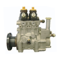
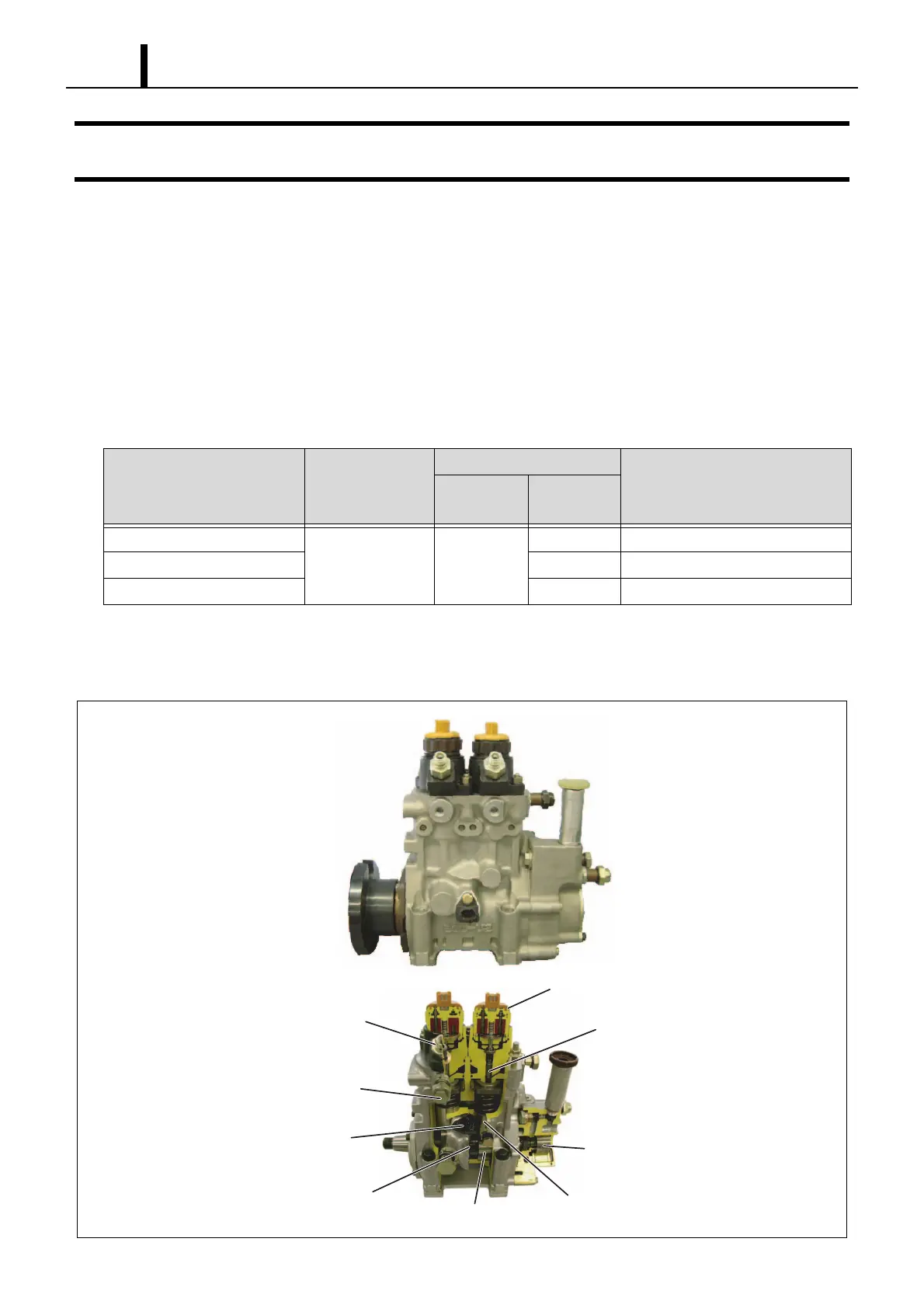
3.1 HP0 Type
(1) Construction and Characteristics
• The HP0 supply pump is mainly made up of a pumping system as in conventional in-line pumps (two cylinders), the
PCV (Pump Control Valve) for controlling the fuel discharge quantity, the cylinder recognition sensor {TDC (G) sen-
sor}, and the feed pump.
• It supports the number of engine cylinders by changing the number of peaks on the cam. The supply pump rotates at
half the speed of the engine. The relationship between the number of engine cylinders and the supply pump pumping
is as shown in the table below.
• By increasing the number of cam peaks to handle the number of engine cylinders, a compact, two-cylinder pump unit
is achieved. Furthermore, because this pump has the same number of pumping strokes as injections, it maintains a
smooth and stable rail pressure.
Number of Engine Cylinders
Speed Ratio
(Pump: Engine)
Supply Pump
Number of Pumping Rotations for 1
Cycle of the Engine (2 Rotations)
Number of
Cylinders
Cam Peaks
4 Cylinders
1 : 2 2
24
6 Cylinders 3 6
8 Cylinders 4 8
Feed Pump
Delivery Valve
Cam x 2
PCV (Pump Control Valve)
Tappet
Element
Cylinder Recognition Sensor
(TDC (G) Sensor)
Pulsar for TDC (G) Sensor
Overflow Valve
Q000768E