Repair Section
2
–
102
(2) Fuel leak check
• Connect the DST-2 to the vehicle-side test connector.
• With the vehicle idling, perform the active test by following the instructions on the DST-2 display.
System selection screen: TCCS a Active Test
• Verify that there are no fuel system leaks during the active test (when fuel pressure is being applied to the rail.)
4.3 Basics of Electrical/Electronic Circuit Checks
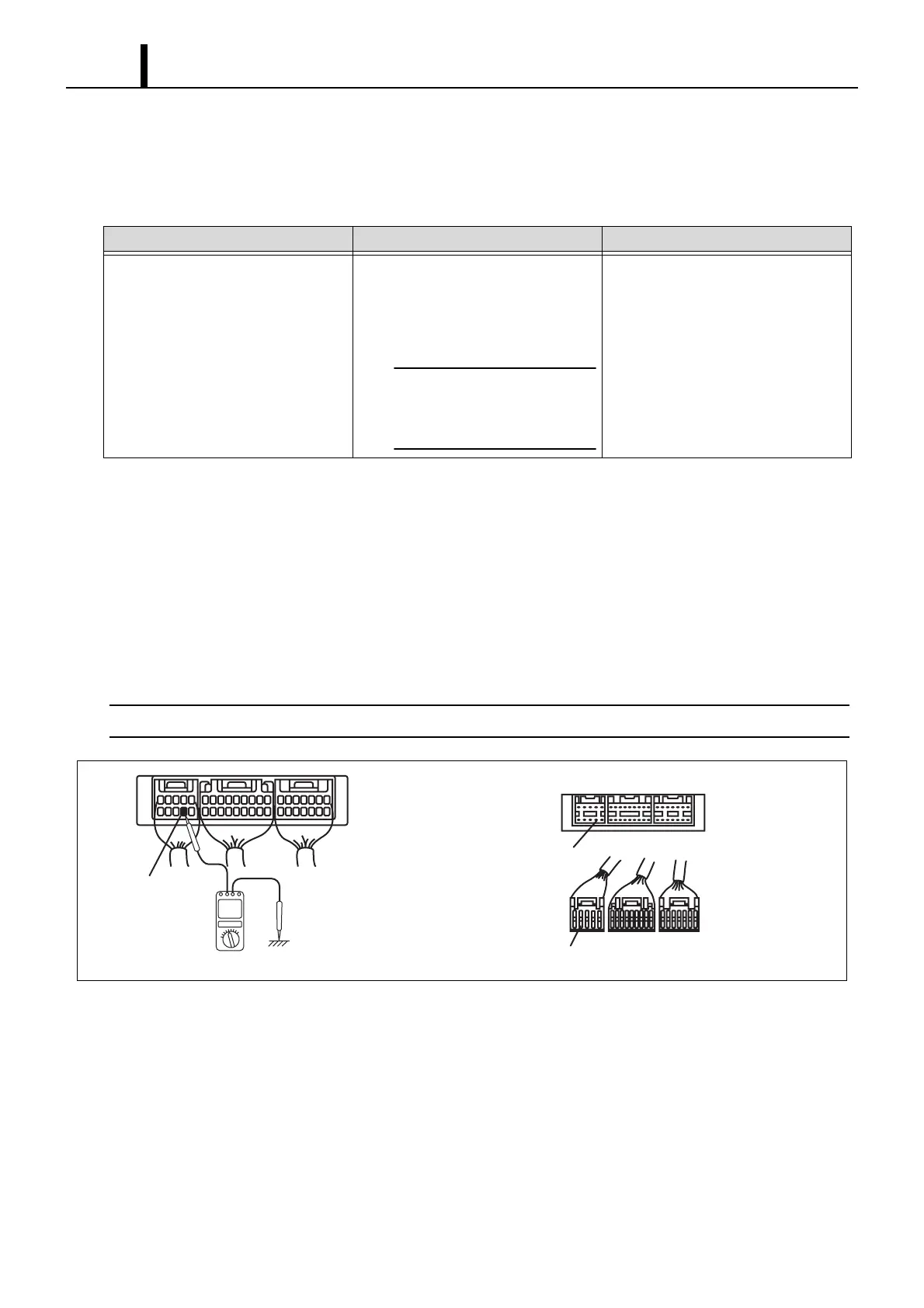
(1) ECU terminal voltage and waveform measurements
• When measuring the voltage and resistance of each terminal, insert the multimeter probe into the rear side of the
wiring harness connector. If connectors are too small for the probe to be inserted easily, insert a fine metal wire into
the rear of the connector and touch the wire to the probe.
< NOTE >
The number of each terminal can be seen from the rear side of the wiring harness.
Item Name Description Control Conditions
High-Pressure Fuel System Check Raise engine speed to 2000 rpm, and
then use the active test to place the
fuel inside the rail under high pres-
sure.
< CAUTION >
Engine speed cannot be
raised by stepping on the
accelerator pedal.
• Following engine warm-up, when
the engine is at idle speed
• The vehicle speed sensor is operat-
ing normally, and speed is 0 km/h.
Q002326E
Ground
Ground
Ground
Engine ECU Side
Wiring Harness
Side