Repair Section
2
–
103
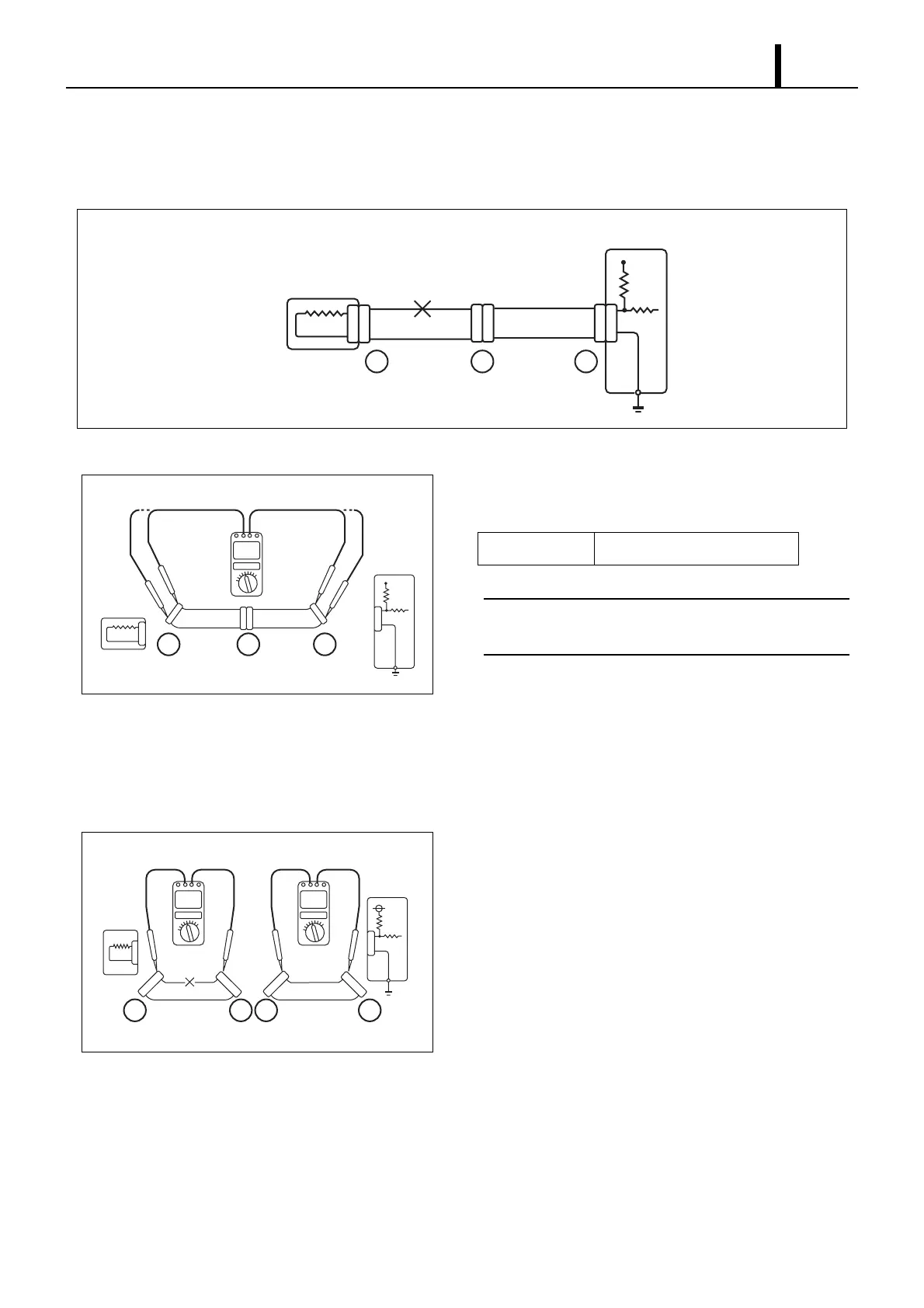
(2) Open circuit check
• When dealing with a wiring harness open circuit like that depicted in diagram 1, check continuity and/or voltage to
determine the location of the open circuit.
Continuity Check
1) Remove connectors "A" and "C", and then measure resis-
tance between the two.
< NOTE >
Measure resistance while gently shaking the wiring har-
ness up and down, and side-to-side.
2) As shown in diagram 2, there is no continuity (open circuit)
between terminal 1 of connector "A" and terminal 1 of con-
nector "C". However, there is continuity between terminal 2
of connector "A" and terminal 2 of connector "C". Therefore,
there is an open circuit between terminal 1 of connector "A"
and terminal 1 of connector "C".
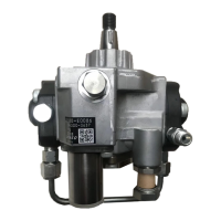
3) Remove connector "B" and measure the connector resis-
tance.
4) As shown in diagram 3, there is continuity between terminal
1 of connector "A" and terminal 1 of connector "B1". Howev-
er, there is no continuity (open circuit) between terminal 1 of
connector "B2" and terminal 1 of connector "C". Therefore,
there is an open circuit between terminal 1 of connector "B2"
and terminal 1 of connector "C".
Q002327E
Diagram 1
Engine ECU
Sensor
Open
Circuit
1111
2222
ABC
Q002328E
Diagram 2
Sensor
Engine
ECU
1
22
1
2
ABC
Standard Value 1Ω or less
Q002329E
Diagram 3
Sensor
Engine
ECU
1
2
1
2
1
2
1
2
ACB2B1