Repair Section
2
–
104
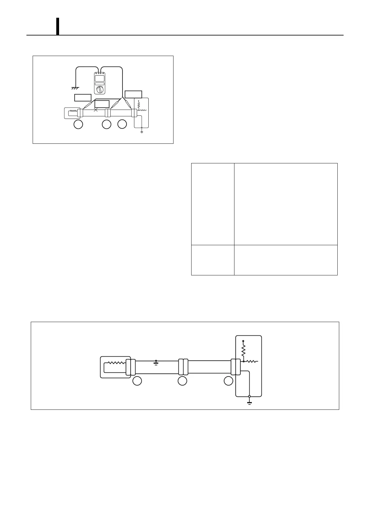
Voltage Check
1) For the circuit that applies voltage to the ECU connector ter-
minals, check for an open circuit by performing a voltage
check.
2) As shown in diagram 4, with all connectors connected, mea-
sure the voltage for the ECU 5 V output terminal between
the body ground and terminal 1 of connector "A". Next mea-
sure voltage for terminal 1 of connector "B" and terminal 1 of
connector "C" in the same fashion.
3) The faulty circuit and measurement results are shown be-
low.
(3) Short circuit check
• As shown in diagram 5, if there is a short in the wiring harness ground, perform a "Ground Continuity Check" to de-
termine the cause of the short.
Q002330E
Diagram 4
Sensor
1
22
11
2
A
BC
0 V
5 V
5 V
Measurement
Results
• Voltage between terminal 1 of con-
nector "A" and the body ground is 5
V.
• Voltage between terminal 1 of con-
nector "B" and the body ground is 5
V.
• Voltage between terminal 1 of con-
nector "C" and the body ground is 0
V.
Faulty Item
There is an open circuit in the wiring
harness between terminal 1 of connec-
tor "B" and terminal 1 of connector "C".
Q002331E
Diagram 5
Sensor
Engine ECU
Short
Circuit
#$%